MegaSquirt PNP Pro Documentation
Model/Vehicle specific installation guide for model MSPNPP-ZR9195 for a 1991-1995 Chevrolet Corvette ZR-1.
Please read all documentation before installing your MegaSquirtPNP EMS and verify that you've followed all steps before starting your engine for the first time.
Physical Installation
For a thorough and professional installation, you will need the following items:
-
10mm socket and ratchet
-
Flat Head Screw Driver
-
Zip Ties
-
Diagonal Wire Cutters
-
Laptop with TunerStudio installed
The ECU is located under the hood, just forward of the driver's side firewall and behind the wheel. To begin, open the hood and locate the ECU. It is secured to its tray with four nuts.
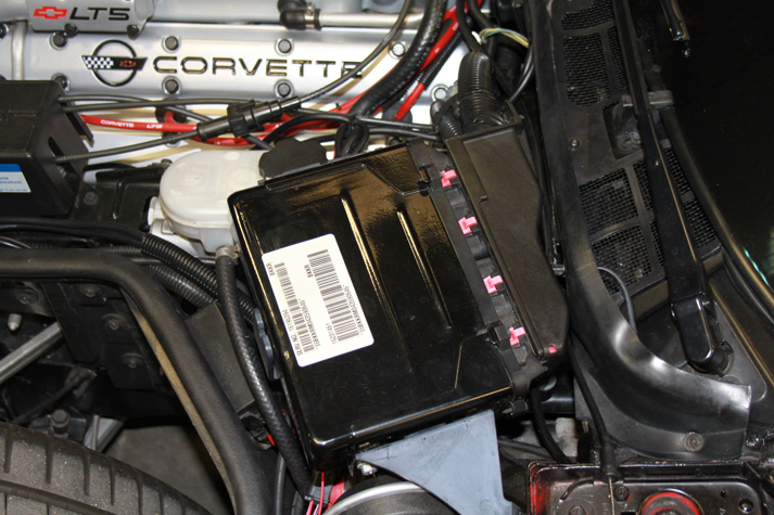
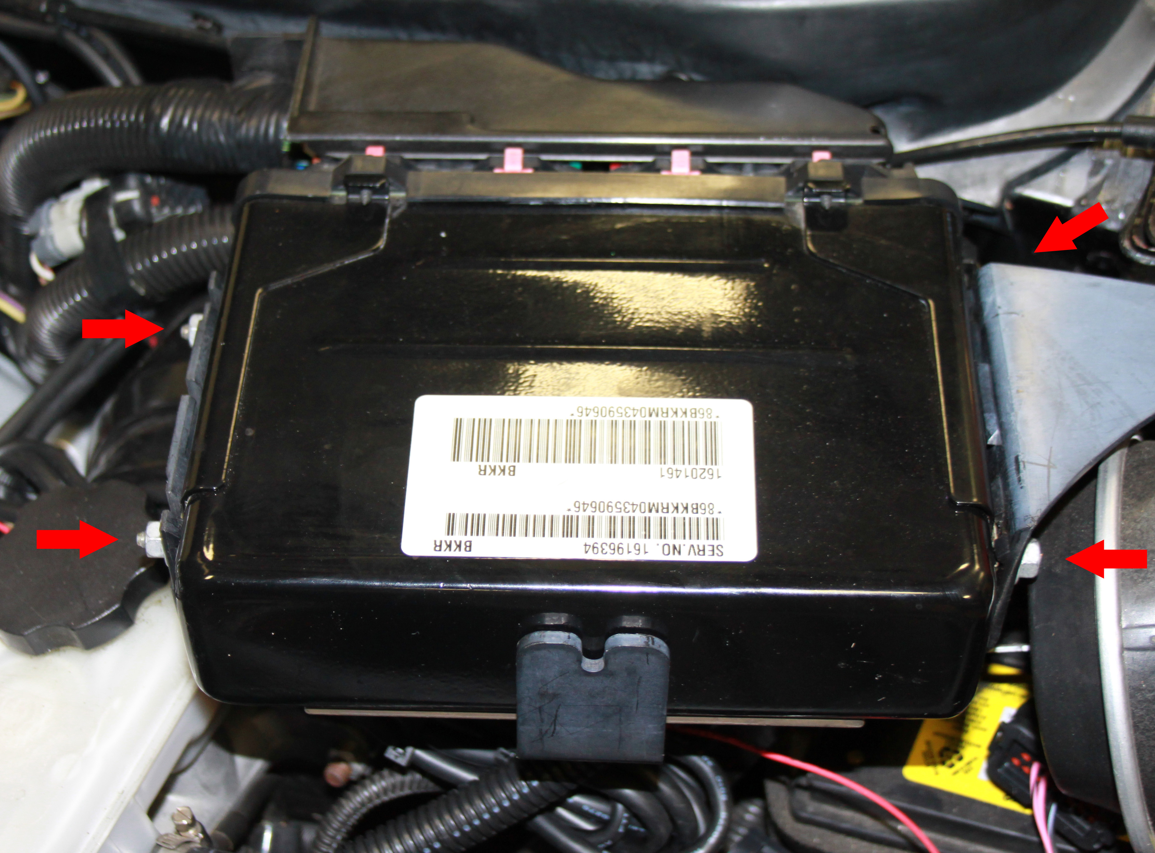
First, remove the four nuts securing the ECU to the tray.
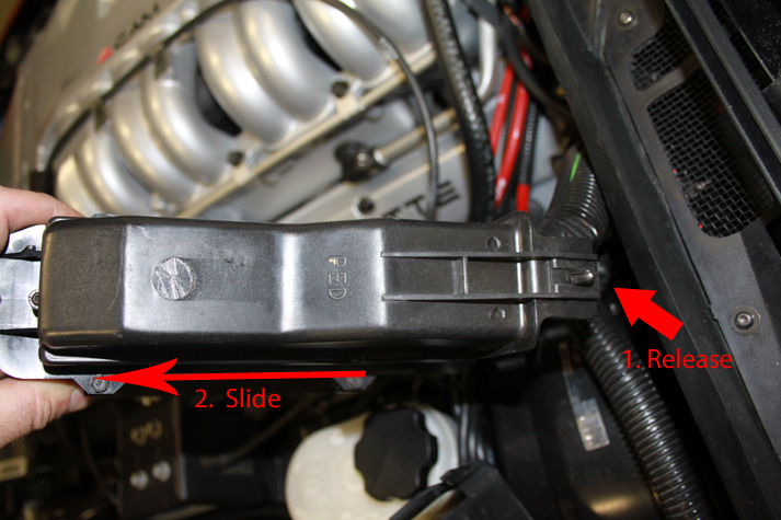
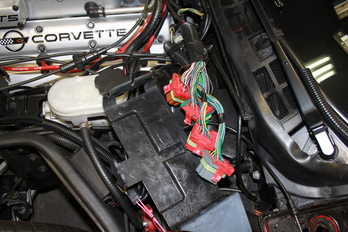
A plastic cover protects the harness wiring on the connector size of the ECU. Lift the ECU out of the tray and locate the plastic cover. It is secured to the harness with a single compression pin. Squeeze the locking fingers of the pin and push it through the hole in the cover, freeing the harness. Once free, slide the cover off of the connector assembly toward the driver's side of the car.
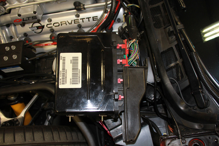
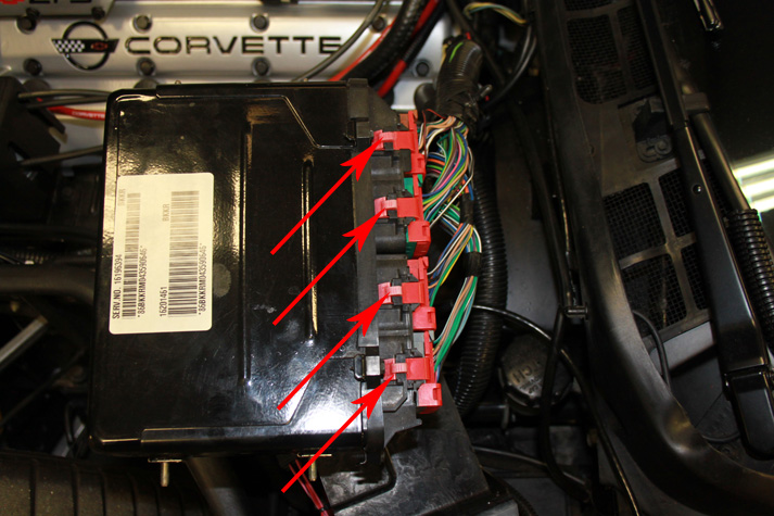
With the harness cover removed, remove each of the four connectors from the ECU. This can be difficult as the connectors and their clips are a tight fit. Furthermore, the black plastic tends to become brittle over time and will crack if the connectors are forced. For each of the four connectors and without the use of tools, squeeze inwards using your thumb and forefinger on the top and bottom tabs of the connector Once the clips are released, pull outward against the body of the connector and away from the ECU. Slightly rocking the connector back and forth helps with removal. Do not pull on the wires themselves.
The original ECU can now be removed from the vehicle.
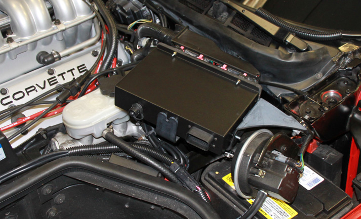
Installation of the MSPNP is the reverse procedure. With the MSPNP logo facing upwards, plug in each of the for connectors; they are keyed to fit only one way into their respective sockets. After the connectors are secured, slide the protective harness cover back into place and secure with the compression pin. Place the MSPNP into the tray and secure with the four nuts provided.
Connecting a USB Cable
This MSPNP model is a water-tight by design. Therefore, it employs the use of water-tight cabling and accessories. The supplied USB cable can remain attached to the MSPNP at all times, however, the PC side of the cable must be protected from the elements. If you choose not to leave the USB cable in place, it is necessary that the waterproof cap remain in place.
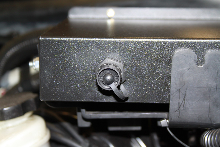
To access the USB port, simply twist the waterproof cap about a quarter turn counter-clockwise and pull away. To connect the USB cable, align and insert the connector. Very little force is necessary. Once inserted, align the locking ring so that it seats properly, then lock it into place using a quarter turn clockwise.
Verifying and Adjusting Base Timing
The ignition timing is set by default in your MSPNP and shouldn't need adjustment. However, if you choose to verify the base timing, it will be necessary to use a piston-stop and a subsequently apply a reference mark on the crankshaft pulley and timing cover. The following steps will require the use of a timing light and a laptop with a copy of TunerStudio running.
-
Connect a timing light on the cylinder #1 spark plug wire. If an inductive timing light is used, you'll need to remove the coil pack and source a standard plug wire. Otherwise, a digital level timing light will be required. Use all due caution here, as secondary ignition voltage can be as high as 100,000 volts or more. Also ensure that the timing light's cords can not get tangled in moving engine parts or burned on hot components.
-
Make sure your tuning laptop is connected to your MSPNP and start your vehicle. If you have not already done so, start TunerStudio MS or TunerStudio Lite. Make sure that your laptop connects to the MSPNP and you are online.
-
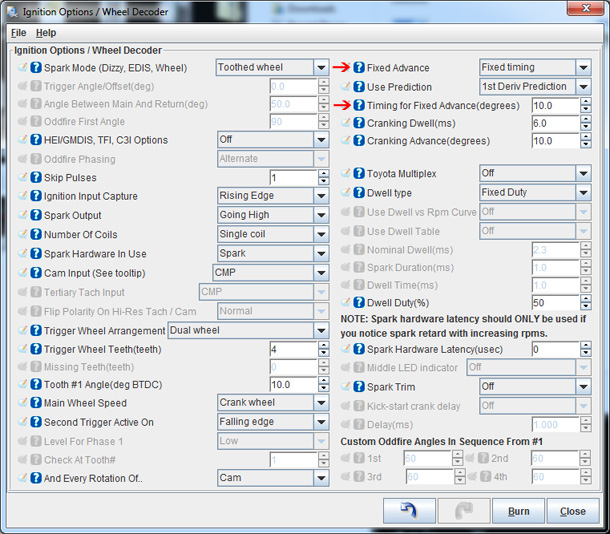
Navigate to the "Basic Setup" tab and click on "More Ignition Settings". If "Fixed Advance" is set to "Use Table", set it to "Fixed timing". This will tell the MSPNP to ignore the ignition table and hold a fixed advance angle. Set this value to 10.0 degrees. Burn these changes and close this menu.
-
Use a timing light to confirm that you have 10 degrees of timing at the crank pulley If you have more timing, decrease the "Tooth #1 Angle". If you have less, increase this value.
-
Once timing has been verified, return the "Fixed Advance" setting to "Use Table" and click burn. Cycle power to the MSPNP (turn the car off and back on). The MSPNP is now commanding timing advance based on the ignition table.
Sensor Calibration
If you need to recalibrate your temperature sensors, such as after loading firmware, here are the values to use for the stock sensors. These work for both factory CLT, IAT, and oil temperature sensors. GM sensors can use the defaults in TunerStudio. The bias resistor value is 2490.
| Temperature (degrees F) | Temperature (degrees C) | Resistance (Ohms) |
| -40 | -40 | 100700 |
| 86 | 30 | 2238 |
| 210 | 99 | 177 |
Cooling Fan Control
| Menu Location | Output Channel | Function | State | Condition (Default) |
| Advanced Engine -> Prog. On/Off Outputs | PWM/Idle Out 1 | Primary Cooling Fan | On | CLT > 205 deg. F. and RPM > 600 |
| Advanced Engine -> Prog. On/Off Outputs | PWM/Idle Out 3 | Secondary Cooling Fan | On | CLT > 210 deg. F. and RPM > 600 |
Staged Injection Control
The LT5 engine uses a set of secondary runners, butterflies, and injectors to change the dynamics of the engine at certain RPM thresholds. Staged injecton control can ge found uner "Fuel Settings -> Staged Injection".
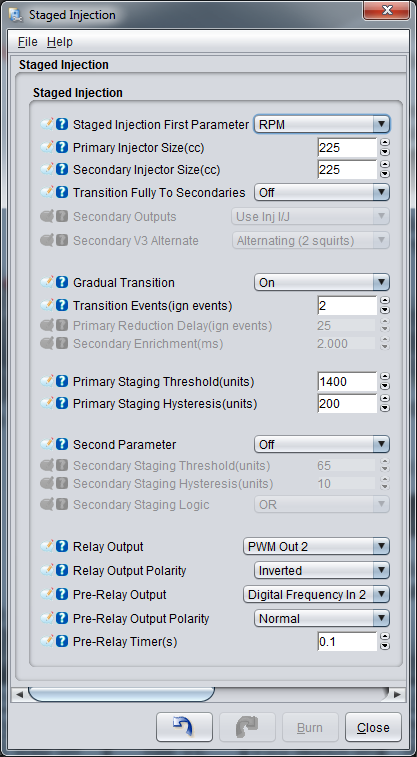
Injectors stage based on RPM trigger @ 1400 rpm. Once enabled, it stays active until RPM < 1200.
When triggered, the ECU activates "Digital Frequency In 2 " (as an output) to trigger the secondary intake system 0.1 seconds ahead of triggering "PWM Out 2" to trigger the secondary injector relays. Both the intake system and secondary injectors are disabled < 1200 rpm.
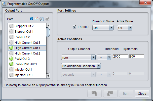
The secondary fuel pump is controlled by "High Current Out 1" and is enabled when RPM > 2000 and, once active, is only disabled when RPM falls below 800.
Power Mode Switch
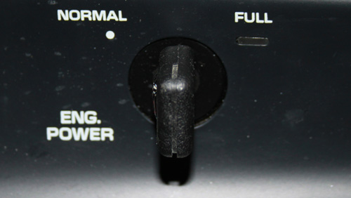
The MSPNP allows multiple configuratons of the power switch located on the dashboard. By default, these features are disabled and left to be used at your discression. Functions such as launch control and table switching, among others, can be tied to the switch. The power switch toggles inputs "DI2" and "DI3" on the MSPNP. When the switch if turned to the left (NORMAL) positon, these I/O points will be turned off. When turned to the right (FULL) position, thise I/O points are turned on.
Auxillary Function I/O Configuration
Below is a listing of funcitons for auxillary I/O used from the MS3Pro module:
| I/O Point | Function |
| High Current 1 (HC1) | Secondary Fuel Pump |
| High Current 2 (HC2) | Boost Control or General Use Output |
| High Current 3 (HC3) | Nitrous Control or General Use Output |
| PWM1 | Primary Cooling Fan |
| PWM2 | Staged Injection Control |
| PWM3 | Secondary Cooling Fan |
| Digital Frequency In 1 (DFIN1) | CEL |
| Digital Frequency In 2 (DFIN2) | Secondary Air Inlet Trigger |
| Digital In 1 (DI1) | Knock Detected |
| Digital In 2 (DI2) | Power Switch Option 1 |
| Digital In 3 (DI3) | Power Switch Option 2 |
| Digital In 4 (DI4) | AC Idle Up |
| Analog Input 1 (AIN1) | Oil Temperature |
Rear Option Connector
An auxilliary connector and harness is provided to allow you to add functionality to your car. Below is the pinout of the rear connector.
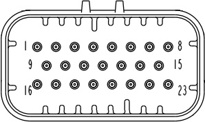
| Pin | Function | Default Function | Notes |
| 1 | Digital In 4 | AC Idle Up | |
| 2 | +5VRef | ||
| 3 | Power Ground | ||
| 4 | Power Ground | ||
| 5 | High Current 2 | Boost Control | |
| 6 | High Current 3 | Nitrous | |
| 7 | Injector I | ||
| 8 | Injector J | ||
| 9 | CANH | ||
| 10 | CANL | ||
| 11 | PWM Out 1 | Primary Cooling Fan | |
| 12 | Knock Input 2 | ||
| 13 | O2 Sensor | ||
| 14 | Analog In 2 | ||
| 15 | Digital Frequency In 1 | CEL | |
| 16 | Ignition A Logic Level | GM "EST" | Optional Seq. Ignition |
| 17 | Ignition B Logic Level | GM "Bypass" | Optional Seq. Ignition |
| 18 | Ignition C Logic Level | Optional Seq. Ignition | |
| 19 | Ignition D Logic Level | Optional Seq. Ignition | |
| 20 | Ignition E Logic Level | Optional Seq. Ignition | |
| 21 | Ignition F Logic Level | Optional Seq. Ignition | |
| 22 | Ignition G Logic Level | Optional Seq. Ignition | |
| 23 | Ignition H Logic Level | Optional Seq. Ignition |
Dashboard Trip Computer
Due to a lack of documentation on the technology used on this control system, functionality of the original trip computer is disabled and an occasional "SYS" fault indicator will be displayed.
7-24-19 - 1.1

