MegaSquirt PNP Pro Manual
Note that this is the main documentation that is applicable to all MSPNP Pro Platform ECUs. For each individual model there is a model-specific addendum to this documentation which addresses the particular installation needs and other unique features of each model of MSPNP Pro
Introduction
What is a MegaSquirtPNP EMS?
The MSPNP Pro is a powerful Engine Management
System that completely replaces the stock ECU for racing applications.
If you're not excited, take a moment and GET EXCITED NOW! You now have
the power to fully unleash all of the potential of your engine both with
your current configuration and with any modifications you'll perform in
the future, no matter how extreme you want to take it!
The
MegaSquirt PNP takes over the functions the stock ECU provides - fuel
control, ignition control, and various other outputs - and lets you
adjust these yourself by connecting a laptop to the MSPNP. It is
designed to plug right into the factory harness where the factory ECU
used to be, and if your engine is pretty close to stock, will easily
start your engine just like the factory computer did. You will, however,
want to fine-tune your MSPNP Pro in order to get the most out of your car's
potential. After all, this ability to tune the fuel and spark maps to
match your engine is what a standalone EMS is all about.
At its core, the MSPNP Pro uses an MS3Pro Module. Bowling & Grippo describe the MegaSquirt as "an experimental do-it-yourself programmable electronic fuel injection controller." With MSPNP, we've already done the experimenting, programming, and wiring needed to make it work with your engine. The MSPNP Pro also has a CANBus output that can be used to talk to expansion modules from DIYAutoTune.com or other MegaSquirt product vendors.
For the majority of you, we've packed all the features you'll ever need right into the core of the unit and you'll likely never care to modify anything. We didn't stop with the base feature set of the MegaSquirt but improved upon it a bit… read on.
We've added functions to the MSPNP Pro that many original factory ECUs do not have. Some of these are built in and use your existing harness, while others require a few changes to the wiring to access since your factory harness didn't support these features. Since MegaSquirt is a speed density system, it is possible to remove the air flow meter (AFM or MAF) to reduce intake restriction if you'd like to. You can set the rev limiter anywhere you want it, and choose either spark cut or fuel cut based rev limiting on most MSPNP Pro applications.
Everything has warning labels...
While most of the warnings will appear in the text discussing what the warning is about, there are a few words of caution before you start installing your MSPNP.
First, the MSPNP Pro is designed for racing applications and other cars that do not need to be emissions legal. It does not use many of the OEM emissions control devices on the engine, nor is its base map tuning calibrated to pass an emissions test.
With the exception of a few specialized models, the MSPNP Pro is not waterproof. Then again, neither are most stock ECUs. It's designed to be put in the passenger compartment, not under the hood or in places where it will get rained or splashed on.
We have thoroughly tested the MSPNP Pro on multiple cars, and the 'base map' tuning should get a stock engine or a mildly modified engine running with no problem. However if you are using this on a modified engine, the tuning may need significant adjustment to properly run your engine. You'll want to dial in the settings before you really push the engine hard. Engines with significant modifications such as those requiring larger injectors may need several settings changed before they will start at all (though setting it up for larger injectors is easy, and covered in this manual). Even if your car is stock, you'll still need to fine tune the base map for your car to ensure your car is safely tuned as all cars are different. You do not want to damage your engine due to assuming the base map is just fine for your car. It's close, but don't assume it's perfect. GET IT TUNED IN!
The MSPNP Pro is designed and tested to work with the stock electronics, wiring harness, and sensors. As a general rule, it will work with almost any modification that works with the stock ECU, and many others that would not have. The only real exception to this is when attempting to use the MSPNP Pro with conflicting electronics. For instance, the MSPNP Pro should not be used with piggyback tuning systems (but why would you?) or other signal interceptors that effect the sensor readings and/or outputs that the MSPNP Pro is using. Attempting to do so may result in unpredictable results, or may simply not work at all and could prevent the MSPNP Pro from running your car properly. As long as you are using the factory ignition system, you can add pretty much any modifications available as long as you tune the MSPNP Pro to work with them. You are only likely to run into trouble if you try changing the crank trigger/cam angle sensor or ignition module to something that does not work with the stock ECU, and in many cases the MSPNP Pro can be adapted to support these as well, though you're getting away from a Plug-N-Play install at that point.
Being a speed density system, your MegaSquirtPNP will let you remove the factory air flow meter. (More details on this below). It calculates the amount of fuel to inject based on RPM and manifold pressure. The MSPNP Pro uses a 4 bar MAP sensor that can handle up to 44 psi of boost if you've turbocharged or supercharged your engine, though if you're not running forced induction you're still just fine with this sensor. It just allows for the big plans you may have down the road.
The settings and table values depicted within this document are for illustration purposes only. Refer to the included base maps for the initial settings and values necessary for your application.
Section Two: Installation
Overview of connectors
Some of the features on the MSPNP Pro EMS are rather obvious as to why they are there, such as the holes to mount it or the logo on the top to let everyone know how awesome you are due to the EMS you that are running. Unlike the MSPNP2, the MSPNP Pro doesn't have a standardized connector for optional features due to the unique nature of its hardware and the vehicles it targets. The pinout for the option connector will be detailed in the individual, model-specific installation guides.
The 9 pin connector is for connecting the MSPNP Pro to your laptop with the provided tuning cable. If your laptop does not have the matching plug, you will need a USB to serial adapter, we recommend the USB-2920 that we sell at DIYAutoTune.com for best results.
There is a small barbed fitting on either the front or back of the MSPNP's case, depending on the model. This is for connecting the MAP sensor. The sensor is designed to work with a rubber hose with around 7/64" - 1/8" inside diameter, which is included in the kit.
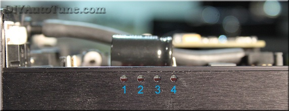
On most models, there are four small holes in the side of the case for viewing indicator LEDs. Looking at the side of the case, from left to right, this what these LEDs do:
- 12 volt power: This light comes on when the ECU has power.
- Logic power (5VDC): Normally, this light comes on whenever the 12 volt power is on. Used mostly for specialized diagnostics.
- Tach pulse: Blinks when you have an RPM signal.
- Configurable: You can configure this LED to turn on or off depending on the conditions you define. It is connected to the output labeled "Ignition G (IGNG).
Tools Required
-
The MSPNP Pro requires very few tools and very little time to install. You will need:
-
Timing Light (adjustable or not can be used, adjustable is nice though)
-
Philips head screwdriver
-
Flathead screwdriver
-
Drill for mounting holes - we recommend mounting it with the included #8 sheet metal screws and a 1/8" drill bit.
-
A laptop or tuning computer to run the included TunerStudio MS software.
-
Socket set and ratchet
Installation Overview
Installing your MSPNP Pro EMS is likely to
take even the first time installer about an hour at most. For the
experienced and/or the professional automotive technician, you're
looking at an hour long install here in most cases.
Please note that
the steps below are just a high-level overview, you must refer to the
vehicle-specific addendum (included in the box with
your MSPNP Pro when it shipped) for your vehicle for the specific step by
step guide for your vehicle. Skipping this vehicle specific
documentation could cause you to overlook important steps. That
said, generally speaking here's an overview of the installation process.
-
Locate and remove the factory ECU. Carefully release the harness connector's latching mechanism and unplug the harness.
-
Plug the MSPNP Pro ECU into the factory harness in place of the factory ECU you just removed.
-
Route the included 1/8" vacuum hose through your firewall and connect to the MAP sensor barb on the MSPNP. Connect the other end to the included 'T' fitting and tee it into the vacuum signal used by your fuel pressure regulator.
-
If using a different size injectors than factory, adjust the REQ_FUEL and other settings for this based on the information in Section Four below.
-
Set your base timing according to the MSPNP's documentation. This is of course, VERY important. You must forget everything you know about setting the base timing on the factory ECU except for where you point the timing light. You MUST use the MSPNP's instructions to properly set your timing. The ECU cannot command proper timing until you synchronize it's commanded timing with the actual timing at the crankshaft. It's easy to do, only stressed here due to importance (and the fact that people tend to try and set it like the factory ECU required, and you're not using the factory ECU anymore).
-
Verify all steps in the vehicle specific installation guide for your vehicle have been followed exactly.
-
Start your engine!
-
Tune your MSPNP!
-
Go hit the racetrack!
Section Three: Optional Features
It's now ready for you to start fine-tuning it to match your
particular setup—you can continue to the next section for more on
tuning. However, there are several other connections and mods you can
add to use the MSPNP's extra features. Some examples of this are
MAF/AFM removal to reduce intake restriction, adding an aftermarket
wideband oxygen sensor and controller, or adding a knock sensor to
vehicles that were not equipped with such from the factory.
MAF/AFM Delete
In most cases you can remove the factory MAF or AFM from your vehicle to reduce intake restriction and increase horsepower and torque! See your specific MSPNP Pro model's addendum documentation for details for your specific vehicle.
Wideband O2 Sensor and Controller
The MSPNP Pro supports many common wideband oxygen sensor systems, including the Innovate Motorsports LC-1 and MTX-L products, the Zietronix ZT-2 and ZT-3 (among others), and most other systems that provide a programmable analog voltage output. You will need to install the controller according to the manufacturer's directions and then connect the MSPNP Pro to a programmable analog output from the wideband sensor's controller. You should ground the wideband to the engine block near the factory ECU ground wire to ensure an accurate reading.
There are two ways of connecting the controller to the MSPNP Pro. You can either connect the analog output to an available analog or EGO input on the option connector, or you can cut and splice the oxygen sensor signal wire to the analog output. Note that not all models have a specific EGO input pin on the options connector; models that do not have an EGO pin will normally have one or more analog input channels on the options port. If you use the EGO input pin on the options connector for wideband input, you must disconnect the stock oxygen sensor. Do not ground the oxygen sensor wire if you disconnect it; leave it completely unconnected and taped off if necessary (make sure it can't short to ground or anything else).
After connecting the wideband sensor controller, you will need to change a few settings on the MSPNP. Section Four has the details of how to change this.
Knock sensing (on cars not equipped with factory knock sensors)
he MSPNP Pro is set up to directly accept input from a knock sensor, either at the option connector on the back of the box for cars that do not have a factory knock sensor, or through the factory knock sensor wiring on cars equipped with a knock sensor from the factory. If your sensor is polarized, wire the positive end to pin labeled "Knock sensor input" and the negative end to pin labeled "Sensor Ground". Most knock sensors have no polarity and can be wired either way. See section 4 for how to tune the knock sensing circuit.
Launch control / Flat Shift:
Launch control may be run with either the factory clutch switch or an external switch. If you are using an external switch for launch control, connect an unused digital switched or frequency input to a switch, and connect the other side of the switch to a chassis ground. Launch control will be active when the switch is closed.
Flat shift requires the use of the clutch switch. It enables a different rev limiter when your foot is on the clutch so you can shift while holding the throttle to the floor.
Flex Fuel:
Instead of launch control, the Digital Switched In 1 input pin of the option connector may be connected to a GM flex fuel sensor. To enable this, go to Fuel Setup -> Flex Fuel Sensor. Enable flex fuel and set the sensor port to Digital Switched In 1. The frequency numbers are set up for a stock GM (or Ford Taurus) fuel composition sensor. The low frequency represents the sensor output with pure gasoline, and the high frequency represents pure ethanol. The MSPNP Pro will multiply the pulse width by the Fuel Multiplier % number determined by the measured fuel compensation, and add the Timing Addition value. the timing.
Table switching:
Table switching for fuel and/or spark tables can be enabled in the Table Choices menu and using an unused Digital Switched In or Digital Frequency In pin. Set the switch source to Hardware for the table you wish to switch, and the input pin to the pin you are using for the switch. This will allow you to use the table switching on the option connector. The alternate table(s) will become active when the selected pin is connected to ground. You can use this to have a second fuel or ignition table for race gas or when a nitrous system is active.
Note that the tables this will switch to are called VE Table 3 and Ignition Table 3 so these are the tables you'll tune for use when Table Switching is activated. Table 2 is used for other functions such as multiple load input.
Boost control:
The High Current Out pins on the option connector can be used for boost control. To use boost control, connect one terminal of an electronic boost control solenoid valve to a 12 volt source that turns on with the ignition, and the other terminal to the selected pin of the option connector. The boost control solenoid valve plumbs into the line running from the intake to the waste gate.
NOTE-- while many EBC valves could be used, we recommend using the EBC solenoid we sell. This is the valve we have tested with, and have setup the base maps to support. Assuming you are using this valve, you'll wire it up with the + terminal on the valve pigtail (there's a small plus next to the where the wiring connector plugs in) to a switched 12v source. This valve truly has no polarity though so it can be wired "backwards" without any problems.
Tach Output:
The "Tach output" pin of the option connector, if present on your MSPNP Pro model, provides a 0-12 volt signal compatible with most aftermarket tachometers. Just wire your tachometer's trigger wire to this pin.
Additional Coil Drivers:
Provisions have been included in the MSPNP Pro to remove ignition control from the distributor and allow ignition from a coil pack. These outputs are logic level (0-5VDC), meaning they need additional drivers to properly control an ignition coil. These outputs cannot drive a coil directly and an external ignitor such as our QuadSpark would need to be installed between the coils and MSPNP. Coils with built in drivers would also work. Below is an example wiring diagram depicting the installation of a QuadSpark with the MSPNP:
Section Four: Tuning
Think of this guide as sort of a quick start guide, as well as an explanation of the unique features of the MSPNP. With the MegaSquirtPNP, tuning is not very different from other MegaSquirt varieties, or most other aftermarket standalone ECUs for that matter. If you've tuned another EMS system before, this process will be very familiar as the fuel and ignition tables will be very similar. You can find in-depth information on tuning MegaSquirt in the MS2/Extra Manuals, available online at https://www.megasquirtpnp.com/tuning
Installing the Software Package
The MSPNP Pro comes with a USB thumbdrive that includes TunerStudio, MegaLogViewer, and all the files needed to tune your EMS. If the installation program does not automatically run when you insert the thumbdrive, you can right click the browse to the thumbdrive directory and double-click the Setup.exe file.
To begin, simply follow the prompts as they are presented and the automatic installation will be complete in just a couple minutes. After the software installation is complete, you can open TunerStudio, connect to your powered MSPNP, and ensure that the proper base map is installed. Base maps can be found under "TunerStudioProjects" within your computer's "My Documents" folder.
Working with MSQ files (TunerStudio Maps)
TunerStudio stores the information from MegaSquirt in MSQ files. The MSQ file contains all of the adjustments and settings needed to run MegaSquirt on a particular engine. These let you back up your tuning or compare your settings with other MegaSquirt users.
The MSPNP Pro thumbdrive for your vehicle comes with a base MSQ file. We've tested this map out on a stock vehicle, and it should get most cars with basic bolt-ons to start up and run with no problem. Even if your car is stock, you will want to fine-tune it to your particular engine, as every car varies just a bit. If you've added any significant modifications, you will definitely want to do some good tuning before really pushing your engine to its limits. But if you find yourself getting lost and having trouble with your tuning, you can go back and reload this default tune to make things work again as a baseline.
The base map is intended as just that however: a 'base' map. It was tuned on 93 octane fuel, and in theory is somewhat conservative. Fuel is different from gas station to gas station, and pump to pump, so what is in theory conservative here may be aggressive on your fuel. AT A MINIMUM RUN THE BEST PUMP FUEL AVAILABLE, AND GET IT TUNED IN, AND KEEP RUNNING THAT FUEL OR BETTER. On a stock car EXACTLY like ours, in EXACTLY the same condition, this map should make similar power to stock, maybe a bit better—though we recommend only running premium fuel, and getting the system properly tuned for your car as soon as possible. With this EMS you have full control of all aspects of engine management on your vehicle. You will find you have excellent results when properly tuned. Though giving you that level of control means you also have the power to tune your engine very badly if you improperly tune things, and could even melt down your engine in a hurry if you don't tune the engine properly. The power to tune is just that, very powerful… Do it right the first time, and if you're not confident in your ability to do so, get a professional tuner to assist you on a load-bearing steady state dyno where the maps can be properly tuned in for your car. Once that's done by a qualified tuner, you can rest assured that your engine is safely making all of the power that it can make with optimum drivability.
If you go to File → Open Tune (MSQ) in TunerStudio, you can open a MSQ file and it will load it into your MegaSquirtPNP. This will overwrite all the settings you currently have saved in the MegaSquirtPNP's memory. TunerStudio will confirm that you want to do this. If you see a dialog box appear with a message that there were warnings when you open the MSQ file, you should probably cancel this until you can investigate further. Feel free to contact our support team and we'll help you quickly determine what may be causing the warning.
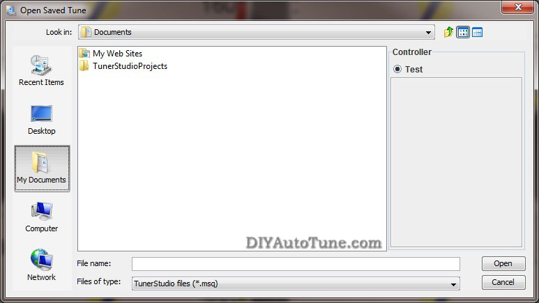
If you want to open a file just to examine it, the safest way is to open it with the MSPNP Pro disconnected. Then you can go to the File menu and select Work Offline. You can then examine the settings in the MSQ file without loading it onto your MegaSquirtPNP.
The "Save Tune" command under the File menu will save your settings. TunerStudio will automatically suggest a name based on the time you have saved the file, or you can specify your own file names. We recommend you save frequently during the tuning process so that you can always revert back if you make a change and find you need to back out.
You can share MSQ files with other MegaSquirtPNP users, though it can be risky business if you are not careful. It's easier and generally safer to copy a MSQ file from another MSPNP Pro user running the same model MSPNP Pro you are running, but you can also use maps from standard MegaSquirt if you first set the spark, input and output settings to match those in the MSPNP Pro base map. There are a few words of caution when sharing MSQ files. First, you will need to make sure it is from a similar version. Do not try loading any MSQs from MS1 or MS2 variants. You will see a warning if you try to load one from an incompatible firmware version; don't ignore this warning.
Second, non-MSPNP MegaSquirt (such as a DIY MS model) may use different outputs from a MSPNP. Even the MSPNP's cousin the DIYPNP is not always an exact match. You will want to check to make sure all outputs are assigned to the same channels before loading a non-PNP MegaSquirt map into your MSPNP. If these are not set correctly, you may damage your ignition system or accidentally disable certain features of the MSPNP.
The last potential source of trouble when sharing MSQ files is that a different owner's MSQ file may not be right for your engine. It may be tuned for an engine with different modifications, or may have a few mistakes in it's tuning. Loading an untested/untuned MSQ file just before a race and going out for a few laps without tuning it can be a recipe for disaster.
If you are not 100% sure of what you are doing, then don't. You risk burning your ignitor and coil and/or damaging your ECU. The base map provided is very good and will get you well on your way to a well tuned car, you will need to fine tune your car no matter where you get your 'base map' from, so you're best bet is to put your car on the dyno, using our base map to start from, and dial it in on your car.... no guesswork needed!
Loading firmware
It is very rare to need to load firmware to an MSPNP Pro as you do NOT need to change firmware to handle sensor calibration. You will only need to reflash firmware if you are upgrading to a newer firmware release, or have managed to damage your firmware by overwriting with an incompatible MSQ file, like we just warned you about in the previous paragraphs. If you need to load firmware, here's how to do it. Be sure to unplug your ignition module (or coils) before loading firmware, and do not plug them back in until you have loaded a MSQ file for your car. FAILURE TO DO THIS CAN DAMAGE YOUR COILS OR IGNITION MODULE.
-
Connect the MSPNP Pro to your computer with the serial port.
-
Disconnect your ignition module.
-
Power up the MSPNP Pro on the car.
-
Go into the Program Files/MegaSquirt folder and open the MS3 folder that matches the firmware you wish to load to your MSPNP. If TunerStudio or other tuning software is running, close it.
-
Open the program called ms3loader_win32.exe for windows or ms3loader_linux32bit for Linux.
-
This program will first ask you a couple of questions about loading the code; tell it you have an MS3Pro and which COM port you are using. Be sure you load it with the MS3Pro version of the firmware.
-
It will end with a message stating that verification has succeeded.
Settings that should not be changed
The MSPNP Pro does not lock you out of any of the settings. As the core MegaSquirt EMS platform is very powerful and designed to work on just about any engine running just about any sensors and ignition system available, there are several settings used to configure the ECU in order to allow the use of these sensors and ignition systems. These are critical settings, and installing a non-PNP MegaSquirt EMS must be researched and configured for each vehicle. We've however taken the guesswork out of this with the MSPNP, and you DON'T want to change these settings. We've configured the MSPNP Pro for your ignition already, and changing some of these settings could cause your MSPNP Pro to stop working with your engine, or worse, could even damage your engine or electronics. In addition, there are several settings and options for features not enabled on the MSPNP. Here are some areas which you should not adjust, as well as some settings that should only be adjusted if you have modified your ECU to enable them.
Ignition Settings you don't want to touch unless you know what you're doing
With stock ignition system components (crank and/or cam trigger wheels, ignition coils, ignitors, etc.), many of the ignition settings need to be left as they are. The only reason to adjust any of the ignition settings (including trigger wheel settings and rotary settings) beyond the spark table are to set the base timing, which you must always do once prior to driving your vehicle on the MSPNP. If you are changing the type of coil you are running to an aftermarket coil or ignition module (ignitor) you might need to change the dwell settings. One other scenario in which you might need to adjust these is if you are converting from a distributor to a distributorless ignition.
Fuel Settings you don't want to touch unless you know what you're doing
Do not enable PWM current limiting for the injectors - the MSPNP Pro firmware just ignores this as it's not needed with the addition of the Peak-N-Hold injector circuitry integrated into your MegaSquirtPNP.
Changes to the staged injection or sequential parameters may only work if you have made the appropriate changes to the injector wiring. This is getting away from the PNP (Plug-N-Play) aspect of this product by allowing you to upgrade your ignition system and fueling beyond what the factory allowed for, and is of course not required to use the product on a vehicle with a stock ignition and fuel system. Input and output ports, such as those under the Output Port Settings, Boost Control, and Tacho Output, are hardwired and should not be changed except as specified in the manual. There is also a reference to nitrous control, although nitrous outputs are not installed on the MSPNP. (You may, however, use the table switching input to use a different fuel and spark table for nitrous.)
Idle Control Valve Settings you don't want to touch unless you know what you're doing
You also do not want to change the settings for the type of idle valve unless you actually change out your idle valve to a different valve. We've pre-configured the base idle valve settings to control the factory idle valve on your vehicle's engine. While you may need to fine tune the closed loop control settings, or the PWM Warm-up settings, you don't need to change the base configuration such as the idle valve frequency.
Settings you DO want to change/tune
Your MegaSquirtPNP allows you to tune all of its settings, we don't hold anything back! Again this gives you all of the power to configure your EMS however you'd like. Here are the settings that are particularly important for tuning your MSPNP Pro to get the most out of your specific engine and modifications.
Fuel (VE) and Ignition Tables
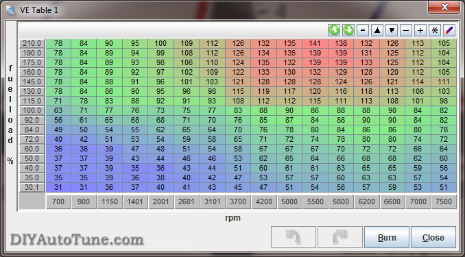
The two main controls, the spark and VE (fuel) tables, are tuned with a similar interface and in the same manner. Both are located under the Basic Setup menu. You can access the table directly and fill in values numerically, or you can toggle the checkbox in the top . When viewing the table directly, note that you can change the bins on the load and RPM axes. You can move these around to accommodate boost or a higher RPM limit, or space a couple bins more closely if you run into any spots that are difficult to tune. The engine load % corresponds to manifold pressure when running speed density (the default for our maps). 100% load is equal to 100 kPa, so engines running forced induction will go over 100% load.
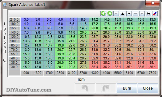
The spark advance table gives the spark advance in degrees as a function of engine RPM and manifold absolute pressure. The best way to tune this table is on a steady-state chassis dynamometer, but you can often get significant power gains by dialing in the ignition on an inertia dyno.
The VE table represents a correction factor from how much fuel the MegaSquirt would inject if you were running a stoichiometric (14.7:1) air to fuel ratio, and the engine actually pulled in a volume of air equal to its own displacement every engine cycle at the temperature and pressure that MegaSquirt measures. You use the VE table to correct for both the engine's actual volumetric efficiency and to change the air/fuel ratio to richer or leaner as the engine requires. Increase the number in a cell to add more fuel at that MAP / RPM combination, and decrease the number to inject less fuel.
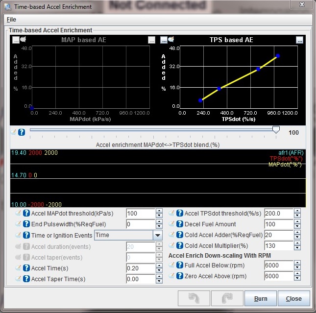
Acceleration Enrichments
The acceleration wizard under the Accel Enrich menu lets you adjust the amount of fuel added when you suddenly hit the gas pedal. There are two graphs, one for MAP based and one for TPS based. The "PW Adder" value is how much extra injector pulse width to add, while the rate number is the change in kPa per second or throttle opening percent per second respectively. For example, 100% TPS per second equals the amount of throttle opening speed needed to go from fully closed throttle to fully open in one second. You can adjust the extra pulse width to increase or decrease the amount of fuel added based on how quickly the manifold pressure changes. The Acceleration Enrichment Settings lets you phase out the acceleration enrichment as RPM comes up. It will start reducing acceleration enrichment when you reach the Low RPM Threshold value, and turn it off completely above the High RPM Threshold value.
The MSPNP Pro also offers an acceleration enrichment mode called Enhanced Acceleration Enrichment. Instead of behaving like the accelerator pump on a carburetor, this feature uses computerized models to determine and accommodate for the fuel that gets stuck to the walls of your intake manifold and allows for very precise tuning. You must have the VE table dialed in correctly in all areas, including overrun and low RPM, for Enhanced Acceleration Enrichment to work correctly. A complete guide to tuning Enhanced Acceleration Enrichment is available here: https://www.msextra.com/doc/ms3/Acceleration_Enrichment.html
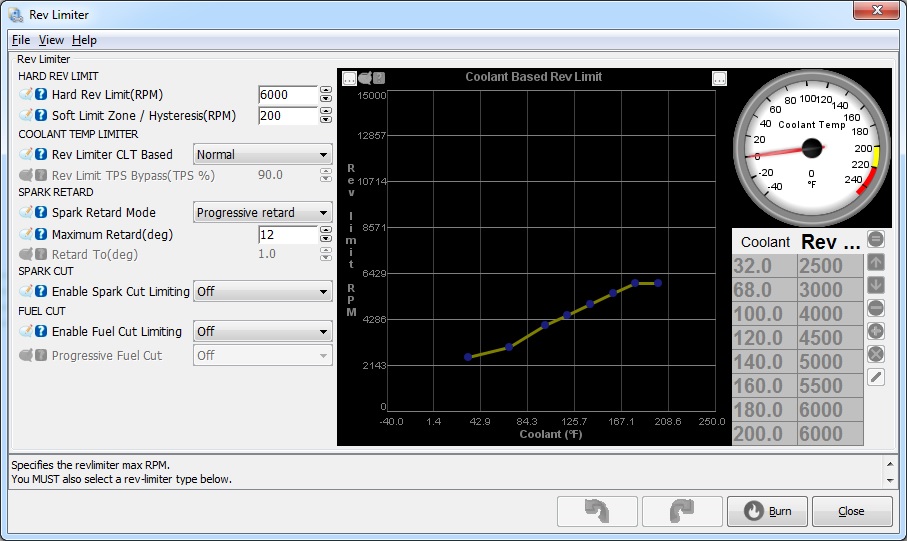
Rev Limiter
MSPNP incorporates a two stage rev limiter, accessible under Basic/Load Settings → Rev Limiter. The soft rev limit simply pulls the amount of timing listed as Maximum Retard from the timing table, while the hard cut can shut down the ignition, fuel, or both. This behavior is all configurable on this screen. You choose whether you want fuel cut, or spark retard at a certain RPM followed by fuel cut a couple hundred RPM higher, or any number of possible configurations. The latter is probably the most common configuration, allowing the power to drop off just before redline, and then fuel cut at whatever redline you choose. Note that a fuel cut will not run your engine lean, it will completely CUT the fuel so that no fuel is flowing. This has proven to be a safe method for use as a rev limiter on N/A and forced induction vehicles.
As a general rule, you should only use the spark cut rev limiter by itself if the car is not equipped with a catalytic converter. Cars with catalytic converters should use the fuel cut rev limiter, either on its own or in combination with spark cut. Turning off the ignition without cutting the fuel will dump raw fuel into the exhaust and can damage the catalytic converter.
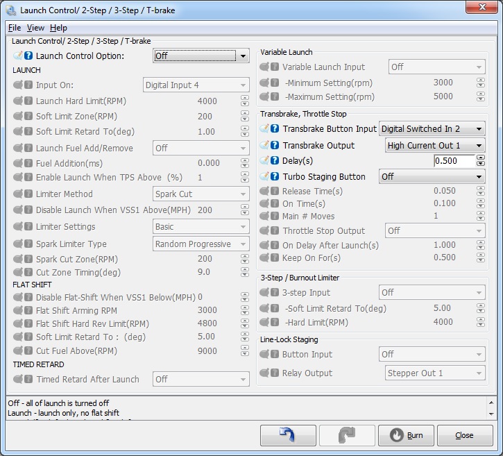
Launch Control
The launch control is based on a rev limiter. This is configured from the Advanced Engine → Launch Control/2-stp/3-step dialog. Often the best way to control this is with the stock clutch switch which opens/closes a circuit based on the clutch pedal position. Note that often this circuit also runs through the neutral safety switch on manual transmission vehicles. This means that if you turn launch control on using the stock clutch switch, it will activate when the transmission is in neutral or when you push down the clutch. So when the trans is in neutral, you'll have a launch control rev limiter. When you push in the clutch and put the trans into first gear, you'll also have a launch control rev limiter (which is when you want it) every time after you first put the car in gear and take your foot off the clutch. When you have the launch control active, the rev limits drop to the limits specified on the launch control screen, letting you rev the engine up to a fixed RPM that you can adjust. When you release the switch, the rev limit is removed and you take off… nice and controlled.
Settings to Change for Modifications (injectors/intake/exhaust/cams/boost/etc.)
Many mods will simply require tuning the VE and spark tables to fit. Modifications to the sensors and fuel system, however, require specific changes to the settings. Here are the recommended changes for some common modifications.
Fuel Injector Compatibility
The MSPNP Pro can drive a wide variety of injectors, including both high and low impedance. Note that the MSPNP Pro ECU's case will run slightly warmer when controlling low impedance injectors. This is normal and nothing to be concerned about.
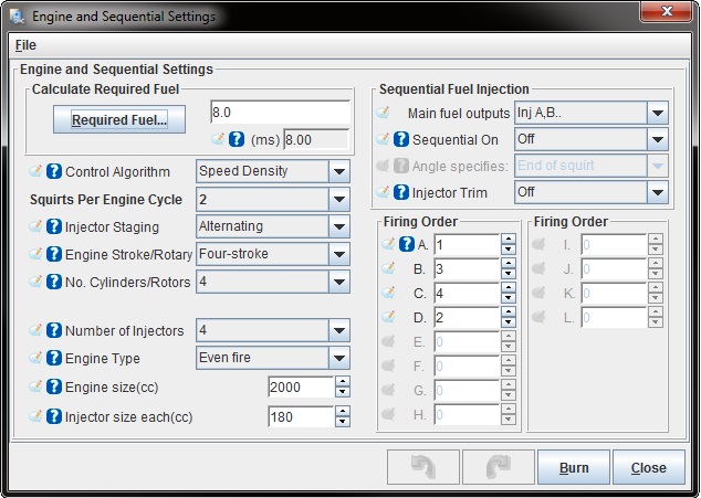
Changing to a different Fuel Injector Size
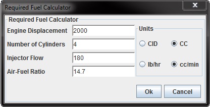
When you change the injector size, MegaSquirt can handle most of the adjustments with just one variable, Required Fuel (aka REQ_Fuel), which sets the base pulse width. TunerStudio can calculate this value automatically for you. To do this, open Basic/Load Settings → Engine and Sequential Settings → Required Fuel. From there you just need to enter your engine size, number of cylinders and injector size, as well as 14.7 for the air/fuel ratio. Don't be concerned if the info in this dialog doesn't match you engine when you first open it up, it doesn't store your info here, just uses it to calculate the new REQ_Fuel number.
There are a few settings which need to be tweaked when changing injector size that do not adjust when you change REQ_FUEL as they are static pulse width (PW) settings, so you will need to adjust these by hand. You may need to adjust the injector dead time found under Fuel Settings → Injector Dead-Time.
After swapping in new injectors and making these adjustments, it's a good idea to make sure your air-fuel ratios are still where they should be. Sometimes the VE table will need a bit of fine tuning due to differences in the way injectors behave, and it's also a math check for the changes you just made. Make sure the air-fuel ratios are good before pushing the engine hard after an injector swap.
Wideband oxygen sensors
MSPNP supports many common wideband oxygen sensor systems, including the Innovate Motorsports LC-1 and MTX-L line, the Zietronix ZT-2 and ZT-3 (among others), and most other systems that provide a programmable analog voltage output. There are a few changes needed to the software settings in order to properly display and use the wideband sensor input properly.
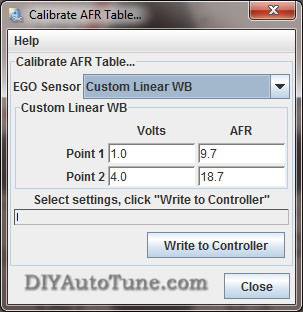
To switch TunerStudio over to a wideband, go to File → Project Properties. Select the Settings tab and set Oxygen Sensor / Display to Wideband, then click OK. Then you will need to tell the MSPNP Pro what voltage output your wideband controller sends. You do this under Tools → Calibrate AFR Table. Most common wideband sensors can be selected from the drop-down menu. If you don't see yours, or your controller has been set to a nonstandard curve, you may select "Custom Linear WB" and enter in its voltage and air/fuel ratio at two points to match a linear output from your wideband to your MSPNP Pro ECU.
Once you have set the MSPNP Pro for your sensor calibration, there are a few other settings you will need to make. You will find most of these in the EGO Control option under the Basic Setup menu. You will need to set the EGO Sensor Type to Single Wide Band. The MegaSquirt will try to maintain the air-fuel ratio specified under AFR Table 1 when running in closed loop mode. The Controller Authority setting limits how much it can change the amount of fuel delivered, so that a faulty sensor can only cause the engine to be off by a small amount. This page also lets you disable the EGO control at full throttle, idle, or when the engine is cold.
The registered version of TunerStudio is also able to tune the VE tables on its own, based on inputs from a wideband sensor. This feature is called VE Analyze Live. The software will adjust the VE tables in a limited range to make the air-fuel ratio match your target settings. Use this feature with caution and make sure your targets and sensor readings are correct before you enable it. You will usually still need to do fine tuning by hand. VE Analyze Live can be used with a narrow band but only to target 14.7:1.
Tuning for Boost
When setting up MSPNP Pro on a boosted engine, you won't have to change very many settings other than properly tuning the VE and Ignition tables for the additional airflow and load. Start with making sure your VE and spark tables go up to the maximum amount of boost you plan to run. Since boost is gauge pressure and MegaSquirt works in absolute pressure, this table will help you convert the amount of boost to the maximum KPA level. These values go just a little above the maximum boost setting. Note that this table assumes sea level pressures as ambient.
-
Naturally aspirated: ~100 kPa (at sea level)
-
5 psi: ~135 kPa
-
10 psi: ~170 kPa
-
15 psi: ~204 kPa
-
20 psi: ~238 kPa
-
30 psi: ~307 kPa
-
40 psi: ~376 kPa
-
44 psi: ~404 kPa
The MSPNP Pro is equipped with a 4 bar MAP sensor, so the maximum amount of boost it can read is 44 psi of boost. While higher amounts of boost will not damage the sensor in most cases, it can damage your engine if you do not tune for it. The MSPNP Pro will not know to add any more fuel above 44psi to compensate because it cannot detect the extra air/pressure, which can result in dangerous lean conditions if you boost beyond that point. If you need a MAP sensor capable of reading higher than 44psi please contact our tech support, we can help!
Since MSPNP Pro is a speed density system, you do not need to recirculate the air in the intake (though you can if you want to). If you prefer, you can go ahead and install a monster blow off valve and vent it to the atmosphere without worrying about having it throwing off your measurements.
Overboost Protection
Overboost protection is available under the Boost/VVT menu → Boost Control Settings menu. The MSPNP Pro base map for factory naturally aspirated vehicles has a default Overboost Protection limit set of 150 kPa which is a bit above 7 psi (depending on ambient pressure in your area). This limit is there to prevent an overboost condition and to protect your motor. If you've added a supercharger or turbocharger to the engine you'll need to adjust this limit to be a bit above the amount of boost you want to run.
When the threshold is reached, injector PW (pulse width) will be cut to 0 for a split second until MAP (manifold pressure) drops back below the limit if overboost protection is turned on (and configured to fuel cut, which is typically how it would be setup). Therefore with the default settings on a factory naturally aspirated vehicle, if you try to boost too near to 150 kPa you will feel the engine cut out when Overboost Protection kicks in. This can feel like a single cut, or it can feel like the car is erratically cutting out and bucking if you stay on the throttle and continue to bounce off the limiter. The Hysteresis value lets you determine how far the boost pressure has to drop before the overboost protection is turned off allowing the injectors to fire again. This 150kpa Overboost Protection limit, and the hysteresis, are very easy to configure in the tuning software on the Overboost Protection dialog under the Extended Menu in TunerStudio MS.
NOTE-- for factory forced induction cars (supercharger or turbo) the default boost cut limit will vary by model. Typically this will be about 20% above the factory boost levels normally seen on the vehicle model. Please see the vehicle specific docs for your MSPNP Pro model/vehicle for further details on the default limit on your car. Tuning is the same as above.
Boost Control
The MSPNP Pro has an electronic boost control feature supporting open and closed loop boost control. Once you have wired this up, you can enable boost control in TunerStudio. In open loop mode, the boost control solenoid puts out a signal at a fixed duty cycle (that is, a percentage of time the solenoid is open) as a function of RPM and the throttle position sensor. This is a bit easier to tune and will generally keep the boost right where you set it, but can drift a psi or two with dramatic changes in air temperature and other variables. You'd be most likely to notice this if for instance you had tuned the car on a 80degF day for 15psi of boost, then drove it on the 32degF day. In that case you might see an extra pound or two of boost. Closed loop boost control is a bit more complicated to tune, but when properly setup allows the ECU target and correct to a specific boost pressure regardless of ambient air temps and other variables that come into play.
NOTE-- while many EBC valves could be used, we recommend using the EBC solenoid available from DIYAutoTune.com. This is the valve we have tested with, and have setup the base maps to support by default.
When running boost control, you'll set up the basic parameters for the valve under the Boost Control screen in the Advanced menu. For our EBC solenoid, we recommend a frequency of 19.5 Hz and a control interval of 20 ms. The Output Polarity setting is Normal. The duty cycles can be a little confusing at first glance: They refer to waste gate opening, not solenoid opening. Set fully closed to 100% duty cycle (this means an open valve applying maximum pressure to the waste gate) and fully open to 0% duty cycle (a closed valve will send no pressure to the waste gate).
Tuning Open Loop Boost Control
If you're using open loop boost control, you'll next need to tune the 'Boost Duty Target' table. And easy way to do this is to start by selecting the whole table (drag a box over all cells), click the "=" button, and set the cells to 10%. Normally, 10% duty cycle won't increase your boost at all, but when you test, watch closely, you may need to use a lower number for your baseline, maybe even all 0's.
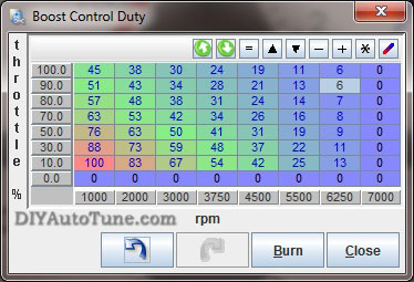
Burn this and try it. See if your boost increases ANY at all over your waste gate only boost levels. Then slowly raise the whole table maybe 5-10% at a time (again, multi-select and fill the whole table is the easy way). Burn it and test it. Datalog this and compare how much boost you made to the prior pull. The pulls need to be in the same gear with all conditions identical, preferably on a dyno, though a track could work if you have a long consistent straight that you can pull 3rd or 4th gear from before the turbo spools (maybe 2000rpm) on up to redline, repeatedly, in a safe environment. You're looking for when you start making more boost. When you do then you can start fine tuning at different RPM ranges. Adding a little more here, pulling a little out there, moving around the RPM columns to make it do what you want it to do, reviewing your logs in MegaLogViewer to see what the results of each pull are. Notice in our example table below, we've got 100%DC in the first column. That's an attempt at making the turbo spool as fast as possible. The GT2560 turbo in our 91 Miata shop car is fully spooled to 13.7psi by about 3500rpm. In order to keep it from spiking though we had to bring the duty cycle way down to 45 by 3200 rpm, then after that we just 'gave it what it needed' to keep the boost at about 13.7psi across the rest of the rpm range all the way to redline. You can see in this table at higher revs it took less DC as the turbo was wanting to make more boost so we had to pull the boost controller back some to control it.
Bottom line, start at low duty cycles, make small changes, and analyze the results of each pull. Remember that as you add boost you're getting into previously untuned areas of your fuel and spark tables and you'll need to adjust those as you go.
If your car has a variable TPS (throttle position sensor) then you can also adjust open loop boost duty cycle based on throttle position, making the waste gate increase or decrease boost at lower throttle positions. Typically you'd reduce DC at lower throttle positions, such as in the cruising speed range where you don't want the turbo boosting to the moon.
Tuning Closed Loop Boost Control
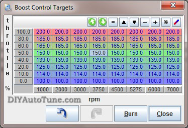
We recommend tuning the open loop boost control before you attempt to tune closed loop boost control. To tune closed loop boost control, first set up the boost control target table. You will enter the desired kPa reading as a function of throttle position and RPM. You should not enter in any values lower than waste gate pressure as the valve cannot reduce boost any further, your mechanical wastegate's pressure is the baseline and can only be added to by electronic boost control. Next you will tune the PID values under Boost Control Settings to make it better hit these targets.
We'd recommend starting to tune CLEBC (closed loop electronic boost control) at a lower boost pressure than you ultimately intend to run. This will allow you to get a handle on tuning this feature prior to running more serious pressures. Before you start, make sure you've adjusted your VE and ignition tables conservatively around and above the boost pressures you are targeting, that means keep the fuel a bit richer than you expect to need, and the ignition a bit retarded from where you expect it to be. To tune the PID parameters, start with 100% proportional gain, 0% integral gain and 0% differential gain. If the boost overshoots above its target get out of the loud pedal quickly, and increase the proportional gain. If it does not spike, you may reduce the proportional gain until you get just a very small amount of overshoot. Leave the proportional gain there. At this point, the boost is likely to creep up slowly after reaching the target. Add a bit more integral gain until the boost stays on target, then increase differential gain until you have minimal overshoot when the turbo first spools up. At this point the boost should track right along with the target boost pressure you've set your MSPNP Pro to target.
Data Logging
All data logging functions can be accessed through the Data Logging menu in TunerStudio.
TunerStudio can log the MSPNP's input and output readings to help you dial in your tune, and it can also be a great diagnostic tool. You can activate this by pressing Alt-L or going to the Datalogging menu and selecting Start Logging. You will be prompted to enter a file name and save it. TunerStudio will start recording after you save the file, and continue saving a data log until you close TunerStudio or turn the logging off. You can then play back these logs with MegaLogViewer to see if your tuning delivers the right air-fuel ratios throughout the RPM range, to monitor commanded ignition timing through the pull, or any number of variables that can help you properly tune your engine. Things such as ignition dwell, manifold pressure & boost, air/fuel ratio, idle valve duty cycle, boost control valve duty cycle, and many other variables can be monitored here. This is an EXCELLENT tuning tool, and is also an invaluable troubleshooting tool should the need arise.
Knock Sensing
The MSPNP Pro employs a Texas Instruments TPIC8101 knock sensor interface chip. This can use either one or two knock sensors, and incorporates a built in, software adjustable band pass filter. The interface allows you to adjust the triggering threshold as a function of RPM and detect knock only at specific crank angles so as to filter out noise occurring when the piston is in a position where it can't possibly be detonating. The MS3-Pro supports cylinder by cylinder knock detection and can identify which cylinder is knocking by crank angle.
The knock settings can be found by browsing to the Ignition Settings → Knock Sensor Settings menu.
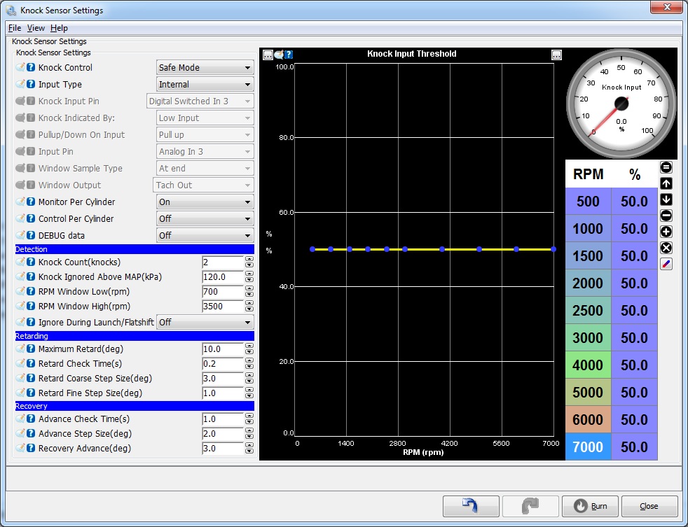
- Knock control: Allows you to change the way the MS3-Pro applies timing retard.
- Disabled: do not use knock feedback for ignition advance control
- Safe Mode: use knock retard, but keep the advance below that which caused knock. This backs the advance 1 small step back and leaves it at that until TPS or MAP changes - or knock comes back. This is "safe mode" scheme is the safest thing for a DIY set-up.
- Aggressive Mode: use knock retard, but keep advance at threshold of knock occurring. That is,
the program advances (up to the timing table value) if it doesn't see knock,
and retards if does see knock. The difference from safe mode is that the timing can be advance
all the way to the table value after knock, not just up to one step below knock. This may result in the knock returning, in which case the timing is retarded again, then advanced slowly, and so on. This approach is also called closed loop knock control. - Input type: On/Off: basic on/off "knock" or "no-knock" external input.
- Analogue: external analogue input proportional to knock signal level.
- Internal: internal knock module.
- Input pin (only for on/off) Which input pin the external module is connected to.
- Knock Indicated By (only for On/off) The logic input level. i.e. when set to 'low' then a 0V signal means there is knock. GM external knock modules fall into this categories.
- Pull-up/down on input (only for On/off) Whether an internal pull-resistor should be applied. When using the normal digital input modes, this should be set to "None."
- Input pin (only for Analogue) Which analogue input pin the external module is connected to.
- Window Sample Type (only for Analogue) Either read single analogue value at end knock window or peak detect.
- Window Output (only for Analogue) Optional digital output for knock window signal.
- Knock Count (knocks): number of knock events detected before control is started
- Knock Ignored above MAP (kPa): no knock retard is implemented above this MAP
- RPM window low (rpm): knock control is implemented above this rpm
- RPM window high (rpm): knock control is implemented below this rpm. This upper limit is desirable as valve train noise will typically mask out the knock sensor signal at higher rpms which could cause false reports of knock.
- Maximum Retard
(deg): maximum total retard when knock occurs. This can be useful to
prevent timing from being excessively retarded (avoiding potential overheating issues) if the senor malfunctions or there are other problems with the knock sensing system. - Retard Check Time (sec): this is the time between knock retard corrections, allows short time step to quickly retard.
- Retard Coarse Step Size (deg): ignition retard step size when 1st knock, make it large to quickly retard the timing and stop knock.
- Retard Fine Step Size (deg): ignition retard step size when knock restarts after it had stopped.
- Advance Check Time (sec): this is the time between knock advance corrections (I.e., timing return to 'normal')
- Advance Step Size (deg): ignition advance step size after knock has stopped.
- Recovery Advance (deg)): this is the change in table advance required to restart advance until knock or reach table value (0 knock retard) process. This only applies in 'Safe Mode'
- Knock input threshold For
analogue and internal modes, this sets a threshold level. If the
measured knock signal exceeds the threshold, then the control system is
started. This allows
different thresholds to be applied to match actual engine behavior. The curve will need to be set empirically by examining datalogs of knock% when operating the engine under safe conditions. - Knock sensor parameters This screen is used with the internal knock processing.
- Band pass frequency - this should be adjusted to suit the resonant frequency of you engine. (Formulae exist on the web for estimating this frequency based on bore diameter.)
- Integrator time constant - internal setting to knock sensor chip. Default is 150us. A larger number will reduce the output level and creates more filtering.
- Number of sensors - how many knock sensors are connected (1 or 2.)
- Monitor per cylinder - when sequential fuel or spark are in operation the code can determine which cylinder the knock signal applies to. This enables the individual cylinder data to be recorded.
- Gain - compensate for sensor sensitivity and distance between cylinder and sensor.
- Sensor - pick which sensor to use for each cylinder. Some engines have multiple knock sensors. In this case, you will usually want to pair the cylinder with whichever sensor is nearest.
- Knock window settings - These are used with both internal and analog knock sensing modes.
Going to the Dyno
Everyone should properly dyno tune any standalone EMS to get the most out of their car and the MSPNP Pro is no different. However, dyno time is very expensive diagnostic time - you want to have your car sorted before you go. You don't want to show up to the dyno with your MSPNP Pro in the box along with your set of 550cc injectors and new boost controller....that's asking for trouble. Go ahead and get the car running on the configuration you'll be tuning before you get there unless you are planning to pay the shop to do all of this for you, in which case you're probably dropping the car off so they can schedule the work. If you're running bigger injectors for example, install the MSPNP Pro first and get that tested and running, then install the bigger injectors, scale the REQ_FUEL and acceleration enrichment on your MSPNP Pro for the bigger injectors, and again make sure it's properly sorted. If you're removing the AFM, go ahead and do that as a separate stage as well, testing afterwards. The idea is to make only one change at a time, so that if there is an issue somewhere you know where to start looking.
Pre-Dyno Maintenance: Make sure there are no leaks, you've got fresh oil, fresh plugs and good wires, your air filter is clean, etc. A full tank of fresh fuel helps too. If you've turbocharged a factory n/a car then you should be running plugs at least one step, sometimes 2 steps, colder than stock. You should probably also gap them a bit tighter than stock. You wouldn't believe how many people get their car to the dyno and aren't ready to have their car on the dyno! Be ready!
To prepare the MSPNP Pro for dyno tuning, disable EGO Correction before you tune by going to Fuel Settings → AFR/EGO Control, and set Controller Authority to 0. After tuning, set it back to 5-10%, or whatever number you had been previously using.
Also disable Acceleration Enrichment by going to Accel Enrich → Time Based Accel or Accel Enrich → Accel-Pump Accl Enrichment Settings (depending on which is available). Zero out the available tables by dragging the graph points to the zero value on the Y-axis. Take note to where these settings are before changing them so that they can be re-entered after tuning.
For best results, have a qualified tuner dial your MSPNP Pro in on a steady state dyno. Loading it into each cell and tuning fuel first, and then doing the same tuning ignition, finally tuning higher throttle doing ramp runs on up to WOT ramp runs. Your tuner will have their own plan but this is what we consider to be the proper order of things. After dyno tuning you can re-enable EGO correction and Acceleration Enrichments and fine tune the Accel Enrichments if they need it. Cranking PW, Warm-up Enrichments, and After Start Enrichments could need fine tuning as well though they are probably close enough to serve you pretty well without adjustment.
Last step is cruise tuning, which on a steady state dyno should be able to tuned 99% perfect by putting low load on the dyno and running the vehicle in various gears all the way down to first. In some cases, it may be easier to fine tune this while actually cruising with the actual load you'll have on the car in a real life cruise situation. You'll be looking for good gas mileage and drivability here while minimizing emissions.
Section Five: The complete warning list
Ignore it at your own peril. These are in no particular order, so please read them all!
The MSPNP Pro is not designed to control emissions equipment and is not intended for use on pollution controlled vehicles. Check local, state, and federal laws governing you in your country/state/city before you even consider such a thing.
If you ever need, or choose, to upgrade or reload your firmware this is very important. You must disconnect power to EITHER the coils or the ignitor when reloading firmware, and load a valid MSPNP Pro map before re-connecting the ignitor/coil. Leaving the coil and ignitor connected when loading code can possibly damage these components. If either of these is disconnected the ignitor and coil will be safe during reflash. Just load a valid MSPNP Pro map, re-connect the ignitor/coil, and you're ready to tune.
The MSPNP Pro is not waterproof and is not designed to be mounted in the engine compartment.
While the base maps provided are typically very close for a stock motor, and should work pretty well on vehicles with minor modifications, it's possible to damage the engine if your tuning is too far away from what your engine needs. If you choose to use an alternate 'base map' obtained from a friend or on the interwebs, verify that any tuning files you have from other users work correctly on your car, as they may be tuned for different modifications or even setup for a different type of MegaSquirt EMS that could even have used different base ignition settings. Ignoring this and using someone else's base map could render your car undriveable if you do not verify these key settings. At any rate, you must make sure your ECU is properly tuned for your engine before racing or otherwise pushing your engine to or near its limits.
The standard MAP sensor in the MSPNP Pro can handle up to 44 psi of boost. It is not able to accurately measure air at higher boost pressure levels, although these won't break the sensor.
If you use the option connector for wideband oxygen input, you must disconnect the stock oxygen sensor. Do not ground the oxygen sensor wire if you disconnect it; leave it completely unconnected and taped off to prevent it from shorting to the chassis or anything else. Do not attempt to plug a wideband oxygen sensor directly into MSPNP Pro without a suitable wideband controller; you should connect the sensor to a controller and the controller to MSPNP.
The registered version of TunerStudio offers a very useful auto-tuning feature called VE Analyzer Live. The VE Analyzer Live function in TunerStudio needs to be used with caution and common sense. Make sure that the target settings are appropriate and the wideband sensor is working correctly before engaging VE Analyzer Live, and check the tuning afterwards to make sure it is working correctly and add any fine-tuning necessary. No computer can replace a qualified tuner…. OK, so that's not entirely true… but you're relying on more than the computer. You're relying on your wideband O2 to be perfect. And have you ever seen what happens to a wideband o2 at wide-open-throttle, or anytime really, when it overheats (which is common on an untuned engine that still has too little ignition advance)? The sensor starts reading crazy numbers. You don't want any computer responding to those wacky numbers by changing the tune of your car and melting your pistons. Do you?
7-24-19 - 1.3

