MegaSquirt PNP Pro Documentation
Model/Vehicle specific installation guide for model MSPNPP-SW0205 for a 2002-2005 Subaru WRX.
Please read all documentation before installing your MegaSquirtPNP EMS and verify that you've followed all steps before starting your engine for the first time.
Physical Installation
All you'll need for a successful installation are some basic hand tools.
For a thorough and professional installation, you will need the following items:
-
10mm socket and ratchet
-
Flat Head Screw Driver
-
Zip Ties
-
Diagonal Wire Cutters
-
Timing Light
-
Laptop with TunerStudio installed
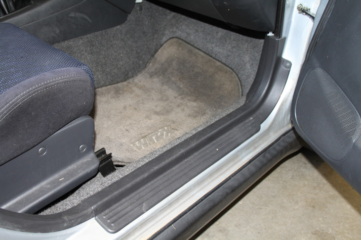
The ECU is located in the passenger's side footwell, beneath the carpet. To begin, you must first remove the door sill. It is secured with a plastic threaded cap, a plastic rivet, and several hidden clips.
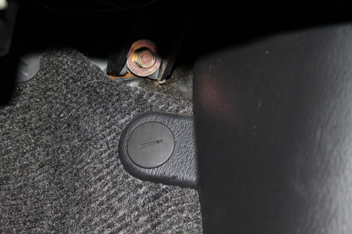
First, unthread the plastic cap the secure the kick panel portion of the sill plate. It's just beneath the glove box, high on the carpet.
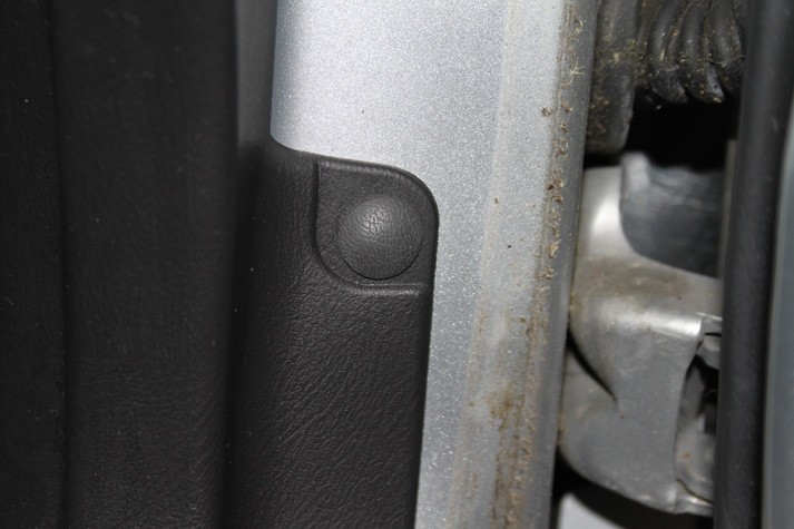
Next, remove the plastic rivet in the door jamb. A small pair of needle nose pliers helps here. Carefully work the pliers behind the rivet head, using caution to not scratch the plastic. Once the pliers are behind the head gently pry and pull the rivet out. Once the threaded cap and rivet have been removed, remove the door sill by grasping the rear lip and pulling firmly and the sill will release from its clips.
After the sill is removed, the carpet needs to be pulled back to allow access to the ECU. A second threaded cap is secures the carpet under the glove box.
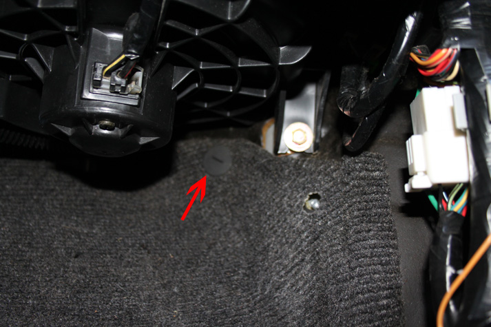
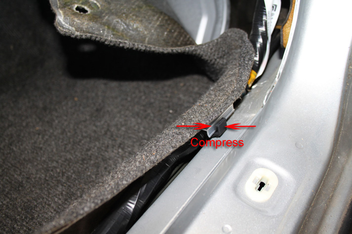
The carpet is secured to the chassis in the door sill with a plastic clip. Using a small flat head screw driver, compress the black portion of the clip and pull the carpet retainer out.
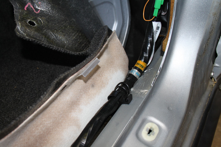
After the carpet clip has been released, the carpet can be pulled back to reveal the ECU cover.
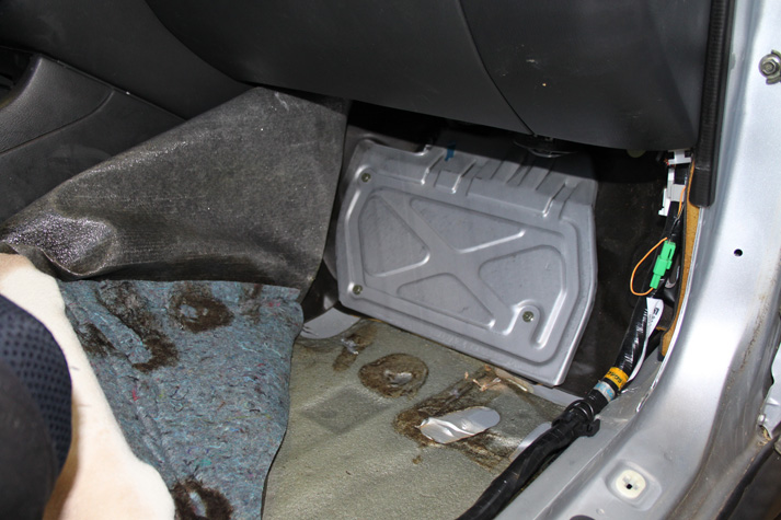
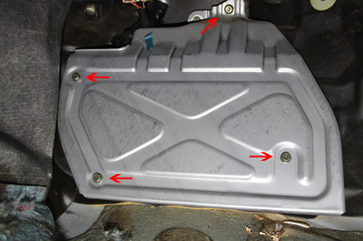
Three bolts and a nut secure the ECU cover. Remove these and the plate will pull away and allow access to the ECU.
Before removing the ECU, remove the plastic cover. It simply sits into place and isn't secured with any hardware.
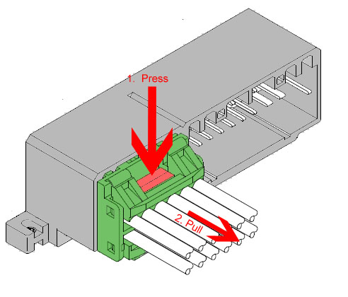
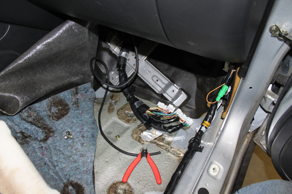
To remove the ECU, 1) disconnect the 5 connectors from the ECU. These connectors can be difficult to release as they're a fairly tight fit in the ECU socket as well as being located in a tight location, so be patient during their removal. Press the locking clips and pull on the connector to unseat them from the socket. Slightly rocking the connector back and forth helps with removal. Be cautious and apply as little pulling force on the wiring as possible.
2) Release the harness clip from the ECU carrier by squeezing the sides of the keeper, and pushing it through the hole.
3) Remove the nuts securing the ECU in place.
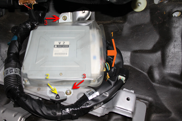
Disconnect/unscrew these items in this order.
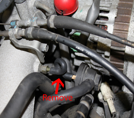
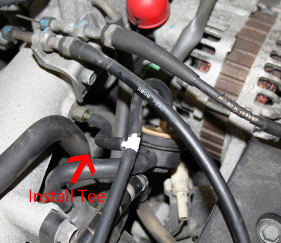
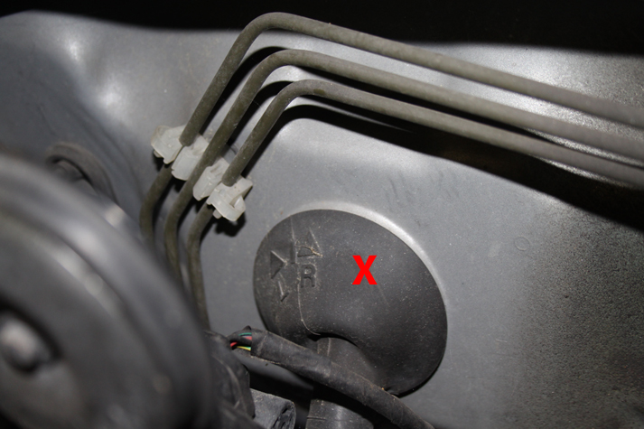
Before installing the MSPNP, you must first run a vacuum line from the engine, through the firewall, and to where the MSPNP will reside. A nipple on top of the intake manifold near the throttle body provides a good source for a vacuum reference. Remove the end of the hose that connects to the damper and install a vacuum tee. Reconnect the other side of the tee to the damper with a short piece of hose.
There is a large rubber grommet in the firewall on the passenger's side corner of the engine bay. CAREFULLY make a slit or hole large enough to pass the vacuum line through. If you use a knife, use extreme caution as there are many wires in this area that you certainly don't want to damage.
Connect the vacuum reference line that will run to the MSPNP to the final port on the tee that you installed and route the vacuum line neatly through the engine bay toward the grommet and secure it with zip ties to prevent movement and entanglement. Pass roughly 3 feet of vacuum hose into the car through the grommet and over to the location of the ECU. Do not trim the hose any shorter than 3 feet.
Plug the MSPNP into the wiring harness.
Unfortunately, there isn't enough room to install the MSPNP in the original ECU location. Fortunately, there is enough room behind the glove box to install the ECU and there's just enough harness length to get there.
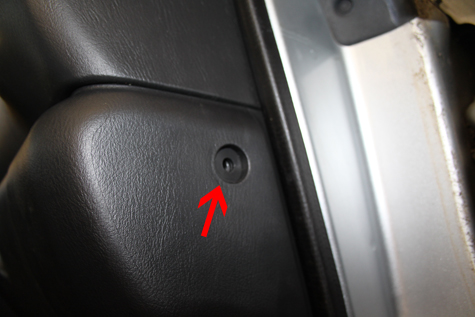
To remove the glove box, first, remove the plastic Philips head screw on the side of the dash board, just inside the door.
The glove box is secured with 9 more screws. Open the glove box, and squeeze the sides as indicated by the direction of the blue arrows below to allow the box to open fully. Remove the 9 screws as depicted by the red arrows in the image below.
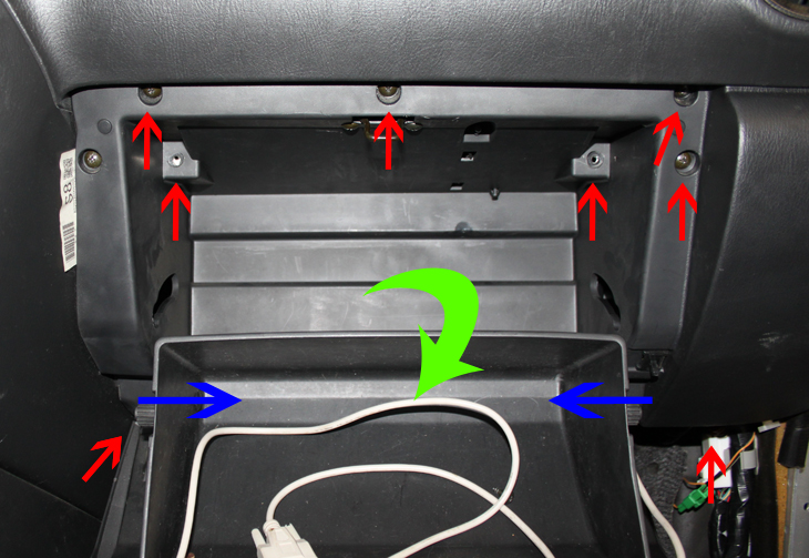
The glove box should pull out and away at this point, but it will be tethered by a single wire harness for the light. Unplug the light and the glove box can be completely moved out of the way.
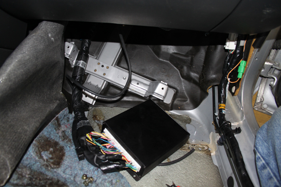
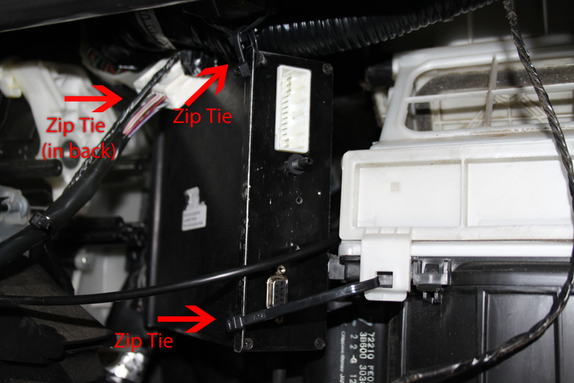
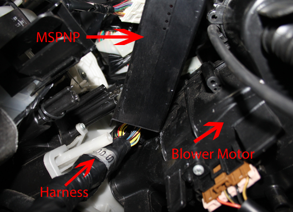
The MSPNP will be secured in place, at sort of an angle, next to the climate control blower with zip ties. As previously mentioned, there is enough slack in the harness to allow the MSPNP to rest here. With everything connected to the ECU, align it as depicted below. The harness may or may not be secured by additional straps or clips. Unfasten any clips as necessary.
View from below:
Route and connect the vacuum hose to the nipple on the back of the MSPNP. Ensure that the hose isn't pinched in the process. Additionally, connect the serial cable to the back of the MSPNP at this time as well.
This completes the basic installation of the MSPNP. Reassembly is the reverse of disassembly.
1) If desired, the original ECU can be installed back into place for
safe keeping since the MSPNP is installed into the dashboard. The
original ECU simply won't plug into anything.
2) Reinstall the ECU
cover plate
3) Replace the
carpet, kick panel, and door sill. Secure with the appropriate
fasteners.
4) Reinstall the glove box
remembering to reconnect the light. During the reassembly process,
the serial cable can be routed so that the free end is stored with in
the glove box.
Verifying and Adjusting Base Timing
Because the factory ECU is no longer in control of ignition timing, it will be necessary to make checks to ensure the MSPNP is accurately delivering the proper timing. Improper ignition advance can cause engine damage if improperly set or is left unchecked.
The MSPNP will have a base ignition map loaded and ready to use. However, it is necessary to ensure that the timing advance being commanded by the MegaSquirt is in sync with what the engine is actually receiving. These steps will require the use of a timing light and a laptop with a copy of TunerStudio running.
-
Connect a timing light on the cylinder #1 spark plug wire. If an inductive timing light is used, you'll need to remove the coil pack and source a standard plug wire. Otherwise, a digital level timing light will be required. Use all due caution here, as secondary ignition voltage can be as high as 100,000 volts or more. Also ensure that the timing light's cords can not get tangled in moving engine parts or burned on hot components.
-
Make sure your tuning laptop is connected to your MSPNP and start your vehicle. If you have not already done so, start TunerStudio MS or TunerStudio Lite. Make sure that your laptop connects to the MSPNP and you are online.
-
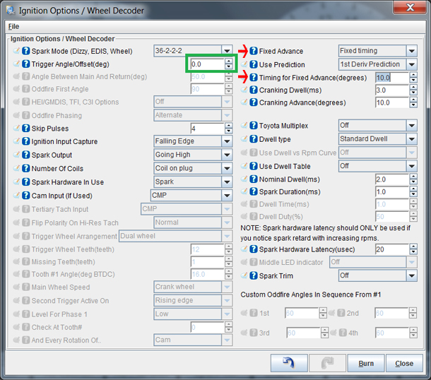
Navigate to the "Basic Setup" tab and click on "More Ignition Settings". If "Fixed Advance" is set to "Use Table", set it to "Fixed timing". This will tell the MSPNP to ignore the ignition table and hold a fixed advance angle. Set this value to 10.0 degrees. Burn these changes and close this menu.
-
Use a timing light to confirm that you have 10 degrees of timing at the crank pulley -- the indent on the pulley will align with "10" on the indicator. If you have more timing, decrease the "Trigger Angle" (green box above). If you have less, increase this value.
-
Close the "Ignition Options" dialog and go back to the "More Ignition Settings" menu under the "Basic Setup" tab. Set "Fixed Advance" back to "Use Table". Burn and close this menu. Cycle power to the MSPNP (turn the car off and back on). The MSPNP is now commanding timing advance based on the ignition table.
Removing the Mass Air Flow Meter
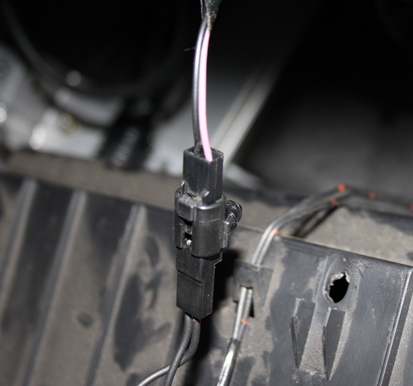
Since the MSPNP calculates engine load using a MAP sensor, the air flow meter is no longer needed. While not necessary, it is recommended to remove the AFM for a small performance increase. At the very least, the air meter should be unplugged and the connector neatly tied away.
Sensor Calibration
If you need to recalibrate your temperature sensors, such as after loading firmware, here are the values to use for the stock sensors. These work for both factory CLT and IAT sensors. GM IAT sensors can use the defaults in TunerStudio. The bias resistor value is 2490.
| Temperature (degrees F) | Temperature (degrees C) | Resistance (Ohms) |
| -4 | -20 | 22000 |
| 68 | 20 | 2500 |
| 176 | 80 | 330 |
Cooling Fan Control
| Menu Location | Output Channel | Function | State | Condition (Default) |
| Advanced Engine -> Prog. On/Off Outputs | High Current Out 1 | Primary Cooling Fan | On | CLT > 195 deg. F. |
| Basic Settings -> Fan Control | Injector I | Secondary Cooling Fan | On | CLT > 200 deg. F. |
Auxillary Function I/O Configuration
Below is a listing of funcitons for auxillary I/O used from the MS3Pro module:
| I/O Point | Function |
| High Current 1 (HC1) | Fan 1 |
| High Current 2 (HC2) | Boost Control |
| PWM3 | Fuel Pump Speed |
| Injector I (INJI) | Fan 2 |
| Injector J (INJJ) | AC Relay |
| Digital Frequency In 1 (DFIN1) | CEL |
| Digital In 3 (DI3) | AC Request |
Fuel Pump Control
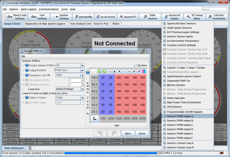
The WRX uses a PWM speed controlled fuel pump. The duty cycle for the fuel pump can by adjusted by navigating to Advanced Engine->Generic PWM Output A.
Tumble Generator Valve (TGV)
The TGV is not controlled by the MSPNP. Instead it is held in a fixed state (open) by jumpers J3 and J4 on the black PCB.
Optional Configurations
Several jumpers are located on the lower, black circuit board inside the MSPNP. These are accessible by removing the top cover and are indicated as depicted below:
J2: Oxygen Sensor Selection
Place a jumper between
"O2 Select" and "Front" to connect the front OE O2 sensor the the MSPNP.
Likewise, connect the jumper between "O2 Select" and "Rear" to connect
the front OE O2 sensor.
J3: Left TGV
Remove jumper to close TGV.
J4: Right TGV
Remove jumper to close TGV.
J9: MAP Select
Selects between the internal MAP sensor and an optionally wired external
MAP sensor.
Rear Option Connector
An auxilliary connector and harness is provided to allow you to add functionality to your car. Below is the pinout of the rear connector.
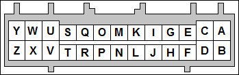
| Pin | Function | Default Function | Notes |
| A | Sensor Ground | ||
| B | Knock Sensor 2 | ||
| C | Analog Input 2 | ||
| D | Analog Input 1 | MAF | |
| E | IAT | ||
| F | External MAP Sensor | ||
| G | CANL | ||
| H | +5VRef | ||
| I | CANH | ||
| J | +12V Ignition | Maximum 0.5 Amps | |
| K | Digital Freq. In 3 | Charge Lamp | |
| L | Digital Freq. In 2 | VSS | |
| M | Digital In 2 | ||
| N | Digital In 1 | Flex | |
| O | Digital In 4 | ||
| P | PWM2 | ||
| Q | High Current 3 | Nitrous | |
| R | High Current 2 | Boost Control | |
| S | Ignition D Logic Level | ||
| T | Injector H Logic Level | High Z or GPIO Only | |
| U | Ignition C Logic Level | ||
| V | Injector G Logic Level | High Z or GPIO Only | |
| W | Ignition B Logic Level | ||
| X | Injector F Logic Level | High Z or GPIO Only | |
| Y | Ignition A Logic Level | ||
| Z | Injector E Logic Level | High Z or GPIO Only |
7-24-19 - 1.1

