MegaSquirt PNP Pro Documentation
Model/Vehicle specific installation guide for model MSPNPP-MM9900 for a 1999-2000 Mazda Miata.
Please read all documentation before installing your MegaSquirtPNP EMS and verify that you've followed all steps before starting your engine for the first time.
Physical Installation
All you'll need for a successful installation are some basic hand tools. No cutting or drilling of the original sheet metal or bracketry is required.
For a thorough and professional installation, you will need the following items:
-
10mm socket and ratchet
-
Zip Ties
-
Timing Light
-
Laptop with TunerStudio installed
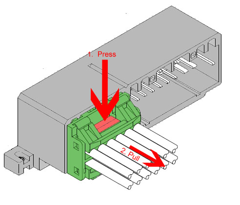
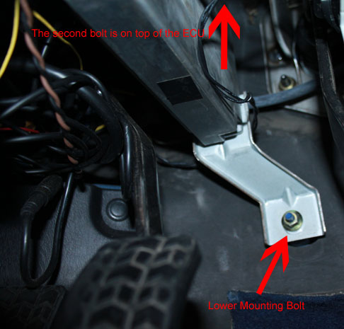
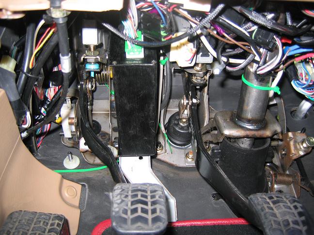
The stock ECU is located under the driver's side dash board next to the steering column and is secured by two bolts. The lower bolt is readily and visually accessible. The upper bolt is on top of the ECU case and a bit more difficult to reach. Remove these bolts and the ECU will drop down. After the ECU is released from the mount, the three connectors will become more accessible and can be unplugged. These connectors can be difficult to release as they're a fairly tight fit in the ECU socket as well as being located in a tight location, so be patient during their removal. Press the locking clips and pull on the connector to unseat them from the socket. Slightly rocking the connector back and forth helps with removal. Be cautious and apply as little pulling force on the wiring as possible.
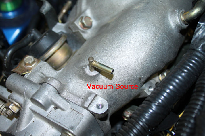
Before installing the MSPNP, you must first run a vacuum line from the engine, through the firewall, and to where the MSPNP will reside. A nipple on top of the intake manifold provides the perfect source for a vacuum reference. Connect one end of the vacuum line here and route it neatly through the engine bay and secure it with zip ties to prevent movement and entanglement.
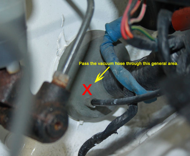
There is a large rubber grommet in the firewall on the driver's side corner of the engine bay. CAREFULLY make a slit or hole large enough to pass the vacuum line through. If you use a knife, use extreme caution as there are many wires in this area that you certainly don't want to damage.
Once the vacuum line is routed to the proper location under the dashboard, connect it to the nipple on the MSPNP. Also, connect the three harness plugs to the MSPNP as well.
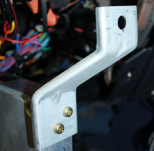
To mount the MSPNP, first remove the lower bracket from the OE ECU. The MSPNP fits well in the stock ECU location between the brake and clutch pedals. Reuse the lower bracket only from the original ECU and secure the MSPNP with zip ties to the lower ECU bracket at the bottom of the unit. At the top of the MSPNP, use zip ties to hold it steady against the clutch pedal bracket.
Verifying and Adjusting Base Timing
Because the factory ECU is no longer in control of ignition timing, it will be necessary to make checks to ensure the MSPNP is accurately delivering the proper timing. Improper ignition advance can cause engine damage if improperly set or is left unchecked.
The MSPNP will have a base ignition map loaded and ready to use. However, it is necessary to ensure that the timing advance being commanded by the MegaSquirt is in sync with what the engine is actually receiving. These steps will require the use of a timing light and a laptop with a copy of TunerStudio running.
-
Connect a timing light on the cylinder #1 spark plug wire. Use all due caution here, as secondary ignition voltage can be as high as 100,000 volts or more. Also ensure that the timing light's cords can not get tangled in moving engine parts or burned on hot components.
-
Make sure your tuning laptop is connected to your MSPNP and start your vehicle. If you have not already done so, start TunerStudio MS or TunerStudio Lite. Make sure that your laptop connects to the MSPNP and you are online.
-
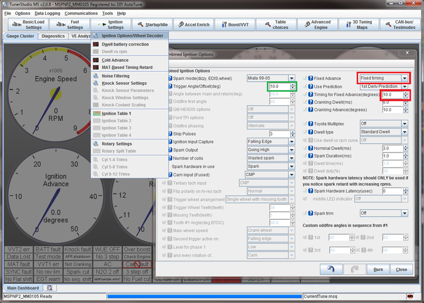
Navigate to the "Ignition Settings" tab and click on "Ignition Options/Wheel Decoder". If "Fixed Advance" is set to "Use Table", set it to "Fixed timing". This will tell the MSPNP to ignore the ignition table and hold a fixed advance angle. Set "Timing for Fixed Advance" to 10.0 degrees. Burn these changes.
-
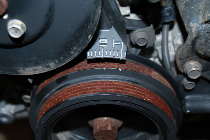
Use a timing light to confirm that you have 10 degrees of timing at the crank pulley -- the yellow mark will align with "10" on the indicator dial and the white mark will align with "T". If you have more timing, decrease the "Trigger Angle" (green box above). If you have less, increase this value.
-
Once the timing is set, click "Burn". Set "Fixed Advance" back to "Use Table". Burn again and close this menu. Cycle power to the MSPNP (turn the car off and back on). The MSPNP is now commanding timing advance based on the ignition table.
Removing the Mass Air Flow Meter
Since the MSPNP calculates engine load using a MAP sensor, the air flow meter is no longer needed. While not necessary, it is recommended to remove the AFM for a small performance increase. At the very least, the air meter should be unplugged and the connector neatly tied away.
Cooling Fan Control
| Menu Location | Output Channel | Function | State | Condition (Default) |
| Advanced Engine -> Prog. On/Off Outputs | PWM2 | Primary Cooling Fan | On | CLT > 195 deg. F. |
VICS Control
| Menu Location | Output Channel | Function | State | Condition (Default) |
| Advanced Engine -> Programmable On/Off Outputs | Injector I | VICS | On | RPM > 5500 |
Auxillary Function I/O Configuration
Below is a listing of funcitons for auxillary I/O used from the MS3Pro module:
| I/O Point | Function |
| PWM2 | Fan 1 |
| PWM3 | Alternator Field Control |
| Injector I (INJI) | VICS |
| Injector J (INJJ) | Fan2/AC Compressor |
| Digital Frequency In 1 (DFIN1) | CEL |
| Digital Frequency In 2 (DFIN2) | VSS |
| Digital In 2 (DI2) | Clutch Signal |
| Digital In 3 (DI3) | AC Request |
Optional Configurations
Several jumpers are located on the lower, black circuit board inside the MSPNP. These are accessible by removing the top cover and are indicated as depicted below:

Default settings indicated in red.
J2: Fuel pump Selection
On European cars with a factory immobilizer, move the jumper to connect
"Fuel Pump" and "Europe w/ immob." Otherwise, leave the jumper
connected to "USA."
J3: Oxygen Sensor Selection
Place a jumper between
"O2 Select" and "Front" to connect the front OE O2 sensor the the MSPNP.
Likewise, connect the jumper between "O2 Select" and "Rear" to connect
the front OE O2 sensor.
J4: MAP Sensor Selection
When this jumper is installed
in the default location, the internal 4-bar MAP sensor will be used.
If the jumper is moved to the location labelled "EXT", an external MAP
sensor wired into the rear option connector will be used. Iif an external
sensor is used, ensure that the scaling is properly set in TunerStudio (Tools -> Calibrate MAP/Baro).
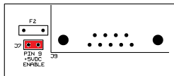
J7: 5VDC Supply on Pin 9 of Serial Connector
The MSPNP is capable of supplying 5VDC to pin 9 of the DB9 serial connector for use with external devices such as wireless Bluetooth adapters. The 5VDC supply is disabled by default. To enable the supply, you must remove the lid (4 screws) and place the jumper across the two pins labelled "J7" located near the serial connector at the corner of the PCB. Note that you will need a #1 philips or a "sharp" #2 philips to remove and replace the lid screws.
Rear Option Connector
An auxilliary connector and harness is provided to allow you to add functionality to your car. Below is the pinout of the rear connector.
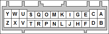
| Pin | Function | Default Function | Notes |
| A | Sensor Ground | ||
| B | Knock Sensor 2 | ||
| C | Analog Input 2 | Alternator Voltage Ref | |
| D | Analog Input 1 | MAF | |
| E | IAT | ||
| F | External MAP Sensor | ||
| G | CANL | ||
| H | +5VRef | ||
| I | CANH | ||
| J | +12V Ignition | Maximum 0.5 Amps | |
| K | Digital Freq. In 3 | ||
| L | Digital Freq. In 2 | VSS | |
| M | Digital In 1 | Flex | |
| N | Digital In 2 | Clutch Signal | |
| O | Digital In 4 | ||
| P | High Current 1 | VVT | |
| Q | High Current 3 | Nitrous | |
| R | High Current 2 | Boost Control | |
| S | Ignition D Logic Level | ||
| T | Injector H Logic Level | High Z or GPIO Only | |
| U | Ignition C Logic Level | ||
| V | Injector G Logic Level | High Z or GPIO Only | |
| W | Ignition B Logic Level | ||
| X | Injector F Logic Level | High Z or GPIO Only | |
| Y | Ignition A Logic Level | ||
| Z | Injector E Logic Level | High Z or GPIO Only |
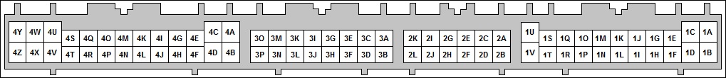
Connector Pinouts for Engine Upgrades
It has become common to upgrade Miatas' engine to those from newer model years. The MSPNPPro has provisions to control all aspects of newer Miata engines including the alternator and VVT. Below is the connector pinout to assist you to assemble your own wiring harness to allow seamless integration of these newer engines.
| Connector 1 | |||
| Connector 1 (Factory Wiring) | |||
| N/C | 1A | 1B | +12V Ignition |
| N/C | 1C | 1D | N/C |
| CEL (via DFIN1) | 1E | 1F | N/C |
| N/C | 1G | 1H | N/C |
| A/C Relay (Injector J Out) | 1I | 1J | N/C |
| N/C | 1K | 1L | N/C |
| N/C | 1M | 1N | N/C |
| Alternator Field Coil (via PWM3) | 1O | 1P | A/C Switch In |
| Charge Lamp | 1Q | 1R | Fan 1 Relay (PWM2) |
| A/C Relay (Injector J Out) | 1S | 1T | Alternator Sense |
| Ground | 1U | 1V | N/C |
| Connector 2 (Optional Wiring) | |||
| CANH | 2A | 2B | Oxygen Sensor |
| CANL | 2C | 2D | Tach Out |
| External MAP Sensor | 2E | 2F | Digital In 1 (Flex) |
| Ground | 2G | 2H | Digital In 4 |
| Ignition C (Cyl 4 Seq.) | 2I | 2J | Ignition D (Cyl 2 Seq.) |
| High Current 1 (VVT) | 2K | 2L | High Current 2 (Boost) |
| Connector 3 (Factory Wiring) | |||
| N/C | 3A | 3B | IAT Sensor |
| Front O2 Sensor (via J3) | 3C | 3D | VSS (DFIN2) |
| CLT Sensor | 3E | 3F | Knock Sensor |
| N/C | 3G | 3H | CMP (Cam) Signal |
| +5Vref | 3I | 3J | CKP (Crank) Signal |
| Tach Out | 3K | 3L | N/C |
| N/C | 3M | 3N | N/C |
| N/C | 3O | 3P | N/C |
| Connector 4 (Factory Wiring) | |||
| Ground | 4A | 4B | Ground |
| Ground | 4C | 4D | N/C |
| TPS | 4E | 4F | Sensor Ground |
| Cyl. 1/4 Ign. Coil (Ignition A Out) | 4G | 4H | Cyl. 2/3 Ign. Coil (Ignition B Out) |
| Clutch Switch (Digitial In 2) | 4I | 4J | Rear O2 Sensor (via J3) |
| N/C | 4K | 4L | N/C |
| IAC (PWM1) | 4M | 4N | Fuel Pump (USA via J2) |
| +12V Ignition | 4O | 4P | Fuel Pump (Europe via J2) |
| VICS Solenoid (Injector I) | 4Q | 4R | N/C |
| N/C | 4S | 4T | N/C |
| N/C | 4U | 4V | O2 Sensor Heater Ground |
| Cyl. 1 Injector (Injector A Out) | 4W | 4X | Cyl. 2 Injector (Injector D Out) |
| Cyl. 3 Injector (Injector B Out) | 4Y | 4Z | Cyl. 4 Injector (Injector C Out) |
10-4-21 - 1.3

