MegaSquirt PNP Pro Documentation
Model/Vehicle Specific information for model MSPNPP-MM9697 on a 1996-1997 Mazda Miata 1.8
Please read all documentation before installing your MegaSquirtPNP EMS, and verify you've followed all steps before starting your engine for the first time.
Physical Installation
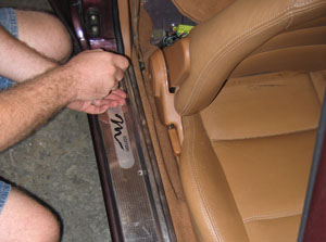
- Remove the right hand door trim panel. Fold and slide the passenger seat forward and lift the carpet behind it to expose the stock ECU.
- Remove the three 10mm nuts holding the stock ECU in place.
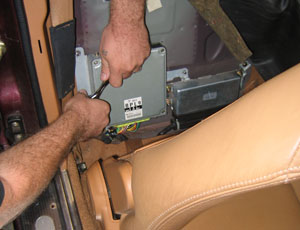
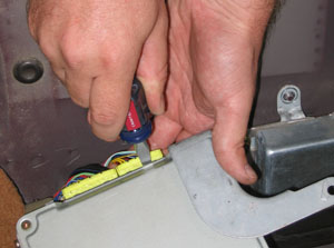
- Fold the ECU over forward (there's just enough room) and remove
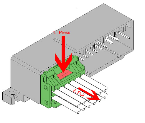
the wiring harness from the ECU. The easiest way to do this is to
reach around the bottom and push down on the release tab with your
finger, while GENTLY prying the connector from the opposite side out
of the ECU with a flathead screwdriver. Do this carefully and you'll
do no damage to your stock harness or ECU.
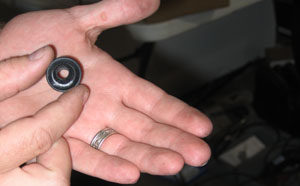
- Now it is time to route the MAP line. Mazda happens to have
provided a plug behind the windshield washer reservoir that's about
the perfect size for the MAP hose.
- Pop the plug out and drill a hole in it. Now the plug is a
grommet. The hole should be just large enough to run the hose
through.
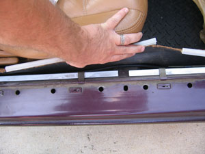
- Pull about 2-3' of the hose through the grommet.
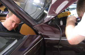
- This next step is much easier if you have two people,
one feeding the hose in from the engine compartment side and the
other one pulling from the passenger compartment. Feed the hose in
through the hole in the engine compartment. Have someone else reach
up behind the firewall insulation and feel for the hole; it's about
as far to the right as it's possible to reach. You will probably
find the hose before you find the hole. Pull the hose in through the
firewall far enough to reach the MSPNP MAP sensor hole.
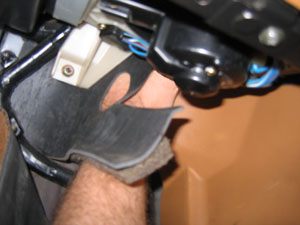
- From the engine side, stick a screwdriver thru the hole pointing down, use it to push the insulation back a bit.
- From inside have someone feel behind the insulation for the screwdriver, this will help them to locate the hole.
- From the engine side, remove the screwdriver and push the hose thru the hole and down. Feed it thru while someone pulls it thru from the inside.
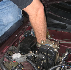
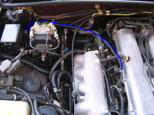
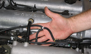
- Inside the engine compartment, route the MAP hose along the
firewall, turning to follow between the intake manifold and valve
cover (over the fuel rail) and use the vacuum tee to connect to the
intake manifold as shown above. You may need to 'fresh cut' the
factory hose by 1cm to get a tight seal as it will have expanded
some. Don't cut the included MAP hose just yet, you'll cut it to
length at the other end.
- Pull any excess hose through the firewall into the passenger
compartment and verify your routing in the engine bay.
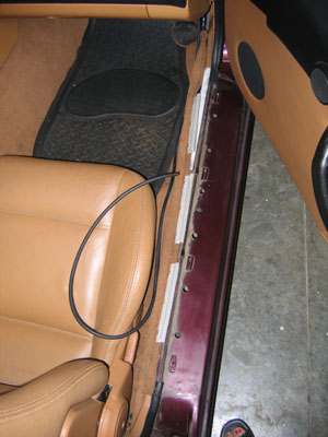
- Back inside the car, lay the MAP hose carefully under the edge of the carpet following the wiring harness to the ECU.
- Plug in the tuning cable first. Then the factory ECU connectors. Lastly plug in the MAP hose.
- Drill holes in the rear firewall and screw the MSPNP to the firewall with the provided sheet metal screws. In our experience two screws up top are usually enough, though four are provided.
- Route the tuning cable between the seat and tunnel and it is
ready to plug in... (or be tucked away when not needed)
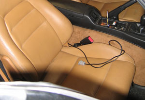
- Fold down the firewall carpet, reinstall the door trim, and tuck the insulation back in place on the front firewall. The ECU is now installed, but you will want to check your timing, as described below.
At this point, it is safe to power the ECU up, but please make sure you load the appropriate startup map for your specific engine before attempting to start the vehicle. Using the wrong startup map may result in a no-start condition, or even engine damage if the engine is driven hard before the correct map is loaded.
Verifying and Adjusting Base Timing
Because the factory ECU is no longer in control of ignition timing, it will be necessary to make checks to ensure the MSPNP is accurately delivering the proper timing. Improper ignition advance can cause engine damage if improperly set or is left unchecked.
The MSPNP will have a base ignition map loaded and ready to use. However, it is necessary to ensure that the timing advance being commanded by the MegaSquirt is in sync with what the engine is actually receiving. These steps will require the use of a timing light and a laptop with a copy of TunerStudio running.
-
Connect a timing light on the cylinder #1 spark plug wire. Use all due caution here, as secondary ignition voltage can be as high as 100,000 volts or more. Also ensure that the timing light's cords can not get tangled in moving engine parts or burned on hot components.
-
Make sure your tuning laptop is connected to your MSPNP and start your vehicle. If you have not already done so, start TunerStudio MS or TunerStudio Lite. Make sure that your laptop connects to the MSPNP and you are online.
-
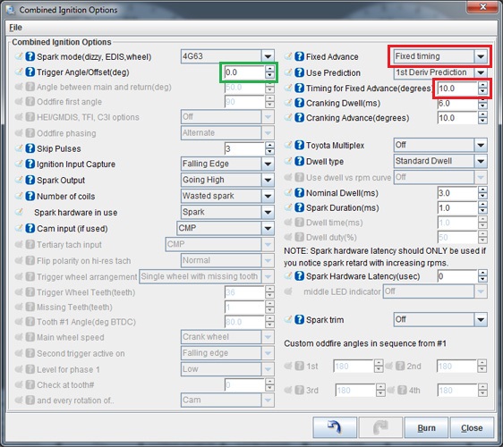
Navigate to the "Ignition Settings" tab and click on "Ignition Options/Wheel Decoder". If "Fixed Advance" is set to "Use Table", set it to "Fixed timing". This will tell the MSPNP to ignore the ignition table and hold a fixed advance angle. Set "Timing for Fixed Advance" to 10.0 degrees. Burn these changes.
-
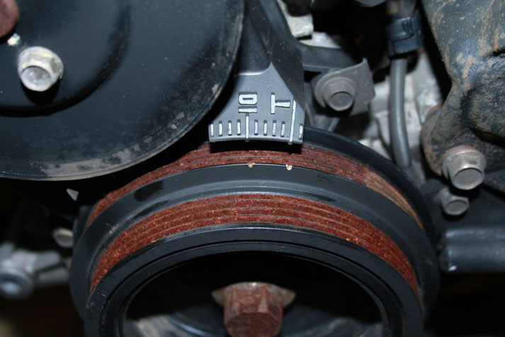
Use a timing light to confirm that you have 10 degrees of timing at the crank pulley. If you have a single mark on your crank pulley, align it with the "10" on the indicator dial. If you have two marks, align the left most mark will align with "10" on the indicator dial and the right mark will align with "T". If you have more timing, decrease the "Trigger Angle" (green box above). If you have less, increase this value.
-
Once the timing is set, click "Burn". Set "Fixed Advance" back to "Use Table". Burn again and close this menu. Cycle power to the MSPNP (turn the car off and back on). The MSPNP is now commanding timing advance based on the ignition table.
Removing the Mass Air Flow Meter
Since the MSPNP is speed density, you don't need to have the restictive factory mass air flow sensor in place. We've found gains of 3 to 5 horsepower by replacing the sensor with a length of straight pipe. You'd think this sensor would be less restrictive than the vane air flow meter on the 1.6, but our tests have shown it's equally bad for horsepower. This does require one wiring change, as there's an air temperature sensor in there. You'll need to substitute a GM IAT sensor with the air flow meter gone. This sensor connects to the third and fourth pins on the IAT connector, as shown in the graphic below. IAT sensors have no polarity, so it does not matter which wire you connect to which pin.
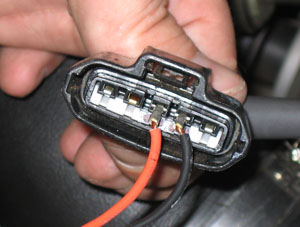
Simply wire a GM Open Element IAT Sensor into your factory wiring harness at the MAF connector. You can poke wires into the MAF connector, or you can cut and splice. Wire one lead of the GM Sensor to the third wire at the MAF Connector, and the other lead of the GM Sensor to the fourth wire at the MAF Connector. The wires should then be folded down over the edge of the MAF connector, and the whole assembly firmly and cleanly wrapped in high quality electrical tape sealing it up. 3M makes tape, such as Super88, that can handle the temps found in engine bays.
After installing the IAT, turn the ignition key on but do not start the engine. Connect to the MSPNP with TunerStudio. Go to the Tools menu and select Calibrate Thermistor Tables. Select Air Temperature Sensor. Select GM from the Common Sensor Values drop down box. Leave the bias resistor setting at 2490.0 ohms. Click Write to Controller. This will update the sensor calibration in the MSPNP.
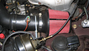
The IAT needs to be located where it will pick up the air temperature after anything in the intake that changes air temperature. So if you are using forced induction, it needs to be downstream of the turbo or supercharger and the intercooler. Here is a picture of an IAT sensor installed in a naturally aspirated car, with a cone filter taking the place of the stock airbox.
Above is an example of one way to bypass your AFM and still get your air filter on there (using a popular turbo kit and charge pipe kit), and more importantly, it shows you exactly where to weld the IAT bung to measure air temp AFTER the turbo, and AFTER the IC. You need to know the air temp as it's entering the engine, nothing else will do us much good. If you are running forced induction this is critical, the stock IAT sensor in the AFM will not do.
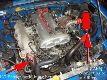
Note: If you are using the MSPNP with a turbo or supercharger:
After you remove the AFM, install the IAT sensor in the location pictured above which is just before the throttle body inlet. The IAT needs to measure the air temperature as it's entering the engine, not the ambient air temperature in the engine bay as would be measured by the AFM. Only by placing the IAT just before the throttle body can an accurate air temperature measurement be taken AFTER the compressor has heated the air, and the intercooler has cooled it. Accurate air temps are needed for proper fueling and ignition advance calculations.
Sensor Calibration
If you need to recalibrate your temperature sensors, such as after loading firmware, here are the values to use for the stock sensors. These work for both factory CLT and IAT sensors. GM IAT sensors can use the defaults in TunerStudio. The bias resistor value is 2490.
| Temperature (degrees F) | Temperature (degrees C) | Resistance (Ohms) |
| -4 | -20 | 16150 |
| 104 | 40 | 1150 |
| 176 | 80 | 330 |
Cooling Fan Control
Your MSPNP has the capability to use the PWM2 output for primary fan control, under Advanced Engine -> Prog. On/Off Outputs. The fan will come on whenever this output is on.
| Menu Location | Output Channel | Function | State | Condition (Default) |
| Basic Settings -> Fan Control | PWM2 | Primary Cooling Fan | On | CLT > 195 deg. F. |
| Startup/Idle -> Air Conditioning Idle-Up | Injector I | Secondary Cooling Fan | On | CLT > 200 deg. F. |
Auxillary Function I/O Configuration
Below is a listing of funcitons for auxillary I/O used from the MS3Pro module:
| I/O Point | Function |
| High Current 1 (HC1) | VVT |
| PWM2 | Fan 1 |
| PWM3 | Alternator Field Control |
| Injector I (INJI) | Fan 2 |
| Injector J (INJJ) | AC Relay |
| Digital Frequency In 1 (DFIN1) | CEL |
| Digital Frequency In 2 (DFIN2) | VSS |
| Digital In 2 (DI2) | Clutch Signal |
| Digital In 3 (DI3) | AC Request |
Optional Configurations
Several jumpers are located on the lower, black circuit board inside the MSPNP. These are accessible by removing the top cover and are indicated as depicted below:
J3, J4: CKP - CAS/Crank VR Select
The position of these jumpers selects the source of the crank position
signal (CKP).
![]()
Jumper
position for CAS CKP signal (default).
![]()
Jumper position for OE crankshaft VR signal.
J6: MAP Sensor Select
When this jumper is installed
in the default location, the internal 4-bar MAP sensor will be used.
If the jumper is moved to the location labelled "EXT", an external MAP
sensor wired into the rear option connector will be used. Iif an external
sensor is used, ensure that the scaling is properly set in TunerStudio (Tools -> Calibrate MAP/Baro).
![]()
Jumper positon for internal MAP sensor siganl (default).
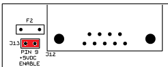
J13: 5VDC Supply on Pin 9 of Serial Connector
The MSPNP is capable of supplying 5VDC to pin 9 of the DB9 serial connector for use with external devices such as wireless Bluetooth adapters. The 5VDC supply is disabled by default. To enable the supply, you must remove the lid (4 screws) and place the jumper across the two pins labelled "J13" located near the serial connector at the corner of the PCB. Note that you will need a #1 philips or a "sharp" #2 philips to remove and replace the lid screws.
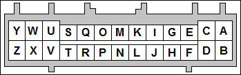
Rear Option Connector
An auxilliary connector and harness is provided to allow you to add functionality to your car. Below is the pinout of the rear connector.
| Pin | Function | Default Function | Notes |
| A | Sensor Ground | ||
| B | Knock Sensor | ||
| C | Analog Input 2 | Alternator Voltage Ref | |
| D | Analog Input 1 | MAF | |
| E | IAT | ||
| F | External MAP Sensor | ||
| G | CANL | ||
| H | +5VRef | ||
| I | CANH | ||
| J | +12V Ignition Out | Maximum 0.5 Amps | |
| K | Digital Freq. In 3 | ||
| L | Digital Freq. In 2 | VSS | |
| M | Digital In 1 | Flex | |
| N | Digital In 2 | Clutch Signal | |
| O | Digital In 4 | ||
| P | High Current 1 | VVT | |
| Q | High Current 3 | Nitrous | |
| R | High Current 2 | Boost Control | |
| S | Ignition D Logic Level | ||
| T | Injector H Logic Level | High Z or GPIO Only | |
| U | Ignition C Logic Level | ||
| V | Injector G Logic Level | High Z or GPIO Only | |
| W | Ignition B Logic Level | ||
| X | Injector F Logic Level | High Z or GPIO Only | |
| Y | Ignition A Logic Level | ||
| Z | Injector E Logic Level | High Z or GPIO Only |
Connector Pinouts for Engine Upgrades
It has become common to upgrade a Miata's engine to one from a newer model year. The MSPNPPro has provisions to control all aspects of newer Miata engines including the alternator and VVT. Below is the connector pinout to assist you to assemble your own wiring harness to allow improved integration of these newer engines.
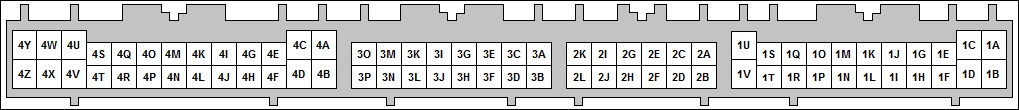
| Connector 1 (Factory Wiring) | |||
| Fan 1 Relay (PWM2) | 1A | 1B | A/C Relay (Injector J Out) |
| N/C | 1C | 1D | N/C |
| CEL (via DFIN1) | 1E | 1F | N/C |
| A/C Relay (Injector J Out) | 1G | 1H | N/C |
| N/C | 1I | 1J | N/C |
| A/C Switch In | 1K | 1L | Clutch Switch (Digitial In 2) |
| VSS (DFIN2) | 1M | 1N | N/C |
| Ground | 1O | 1P | N/C |
| N/C | 1Q | 1R | N/C |
| N/C | 1S | 1T | N/C |
| Fuel Pump Relay | 1U | 1V | N/C |
| Connector 2 (Optional Wiring) | |||
| CANH | 2A | 2B | Oxygen Sensor |
| CANL | 2C | 2D | Tach Out |
| External MAP Sensor | 2E | 2F | Knock Sensor |
| Ground | 2G | 2H | CMP (Cam) Signal |
| PWM3 (Alternator Field) | 2I | 2J | CKP (Crank) Signal |
| AIN2 (Alternator Voltage Ref.) | 2K | 2L | High Current 2 (Boost) |
| Connector 3 (Factory Wiring) | |||
| N/C | 3A | 3B | N/C |
| Front O2 Sensor (via J5) | 3C | 3D | Rear O2 Sensor (via J5) |
| N/C | 3E | 3F | TPS |
| CLT Sensor | 3G | 3H | N/C |
| VRef | 3I | 3J | N/C |
| IAT Sensor | 3K | 3L | Ground |
| O2 Sensor Heater Ground | 3M | 3N | N/C |
| Sensor Ground | 3O | 3P | N/C |
| Connector 4 (Factory Wiring) | |||
| Ground | 4A | 4B | +12V Ignition |
| Ground | 4C | 4D | Ground |
| N/C | 4E | 4F | CKP (Crank) Signal |
| CMP (Cam) Signal | 4G | 4H | N/C |
| N/C | 4I | 4J | N/C |
| Condensor Fan (Injector I Out) | 4K | 4L | Tach Out |
| N/C | 4M | 4N | Cyl. 1/4 Ign. Coil (Ignition A Out) |
| N/C | 4O | 4P | N/C |
| IAC (PWM1) | 4Q | 4R | Cyl. 2/3 Ign. Coil (Ignition B Out) |
| N/C | 4S | 4T | N/C |
| Cyl. 1 Injector (Injector A Out) | 4U | 4V | Cyl. 2 Injector (Injector D Out) |
| Cyl. 3 Injector (Injector B Out) | 4W | 4X | Cyl. 4 Injector (Injector C Out) |
| N/C | 4Y | 4Z | N/C |
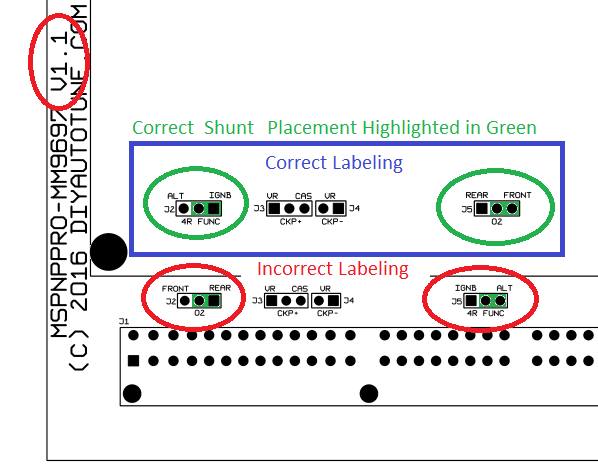
Errata Regarding v1.1 PCBs
An error is
present on the optional jumper configurations on PCBs labeled as version 1.1 as jumper configuration
blocks J2 and J5 are incorrectly labeled. If it is necessary to open the
ECU and adjust the jumper configuration,
the correct jumper labels are highlighted within the blue box below. The shunt
located at J2 should remain in the right most position. This error was
corrected on the V1.2 PCB.
5-5-20 - 1.3

