MegaSquirt PNP Pro Documentation
Model/Vehicle Specific information for model MSPNPP-MM9093 on a 1990-1993 Mazda Miata 1.6L
Please read all documentation before installing your MegaSquirtPNP EMS, and verify you've followed all steps before starting your engine for the first time.
Physical Installation
-
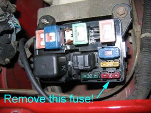
Remove the ST SIGN fuse from the under hood fuse box. You should not put it back in when you finish installation. Do not run the MSPNP with this fuse in place, ever. There are provisions in place to protect the MSPNP if this fuse is left in place, but it isn't meant to be operated in this manner. REMOVE THIS FUSE!
-
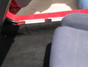
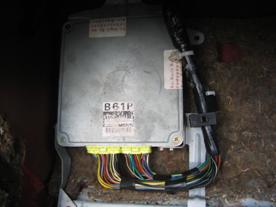
Remove the right hand door trim panel. Pull back the carpet to expose the ECU cover panel at the front of the foot well.
-
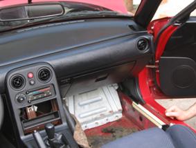
Unbolt the ECU cover panel. It's held in place with four nuts and a bolt at the top right. The same screws that hold the ECU cover panel in place hold the ECU to its mounts, so the ECU can now lift out.
-
There's a small pop-in fastener holding the harness to the ECU frame that will come out when you squeeze it. Needle nose pliers will help with removing this.
-
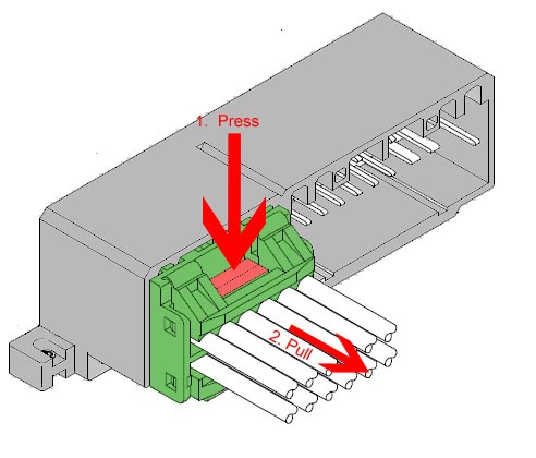
The two connectors will become more accessible and can be unplugged. These connectors can be difficult to release as they're a fairly tight fit in the ECU socket as well as being located in a tight location, so be patient during their removal. Press the locking clips and pull on the connector to unseat them from the socket. Slightly rocking the connector back and forth helps with removal. Be cautious and apply as little pulling force on the wiring as possible. Remove the wiring harness from the ECU. The easiest way to do this is to push down on the release tab with your finger, while GENTLY prying the connector from the opposite side out of the ECU. Do this carefully and you'll do no damage to your stock harness or ECU.
-
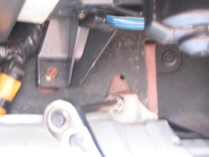
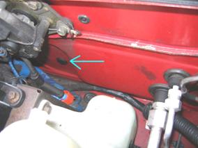
Now it is time to route the MAP line. Mazda happens to have provided a plug behind the windshield washer reservoir that's about the perfect size for the MAP hose.
-
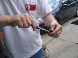
Pop the plug out and drill a hole in it. The hole should be just large enough to run the hose through. Don't use a knife like we did; carefully use a drill bit. If you use a knife and cut yourself then "we told you so."
-
Run the hose halfway through the plug. (pull about 3-4' of it through)
-
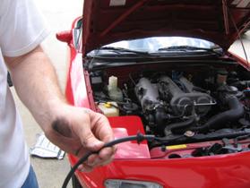
This next step is much easier if you have two people, one feeding the hose in from the engine compartment side and the other one pulling from the passenger compartment. Feed the hose in through the hole in the engine compartment. Have someone else reach up behind the firewall insulation and feel for the hole; it's about as far to the right as it's possible to reach. You will probably find the hose before you find the hole. Pull the hose in through the firewall far enough to reach the MSPNP MAP sensor hole.
-
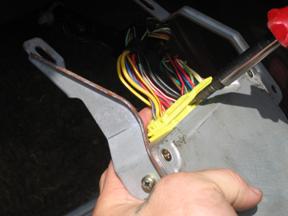
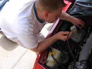
From the engine side, stick a screwdriver thru the hole pointing down, use it to push the insulation back a bit.
-
From inside have someone feel behind the insulation for the screwdriver, this will help them to locate the hole.
-
From the engine side, remove the screwdriver and push the hose thru the hole and down. Feed it thru while someone pulls it thru from the inside.
-
-
Pop the plug back into the firewall and attach the hose to the MSPNP.
-
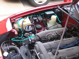
Route the hose under the hood to the front of the intake manifold. You will need to make sure the hose does not have any chance to catch in the throttle linkage, pulleys, and belts, and make sure it's not pinched by the headlight mechanism when they're raised or lowered. Basically remove extra slack and make sure to avoid any moving parts. This blue line shows a suggested route.
-
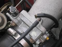
Cut the MAP hose to length and connect it to the nipple behind the throttle body as shown. If you have cruise control, you will need to cut the cruise control line and use the provided "Y" fitting to attach the MAP line. Note that on some cars, we've seen a more stable MAP signal reading if you tee off the fuel pressure regulator at the rear of the manifold. If you experience an unsteady MAP signal, try relocating the MAP sensor line to this point.
-
Plug the wiring harness into the MSPNP.
-
Drill holes in the floorboard and bolt the MSPNP to the floor with the provided sheet metal screws.
-
Connect the tuning cable to the MSPNP and route it under the transmission tunnel trim or another place that will let you reach it for tuning.
-
Reinstall the ECU cover panel and the carpet.
At this point, it is safe to power the ECU
up, but please make sure you load the appropriate startup map
for your specific engine before attempting to start the vehicle.
Using the wrong startup map may result in a no-start condition,
or even engine damage if the engine is driven hard before the correct
map is loaded.
Verifying and Adjusting Base Timing
Because the factory ECU is no longer in control of ignition timing, it will be necessary to make checks to ensure the MSPNP is accurately delivering the proper timing. Improper ignition advance can cause engine damage if improperly set or is left unchecked.
The MSPNP will have a base ignition map loaded and ready to use. However, it is necessary to ensure that the timing advance being commanded by the MegaSquirt is in sync with what the engine is actually receiving. These steps will require the use of a timing light and a laptop with a copy of TunerStudio running.
-
Connect a timing light on the cylinder #1 spark plug wire. Use all due caution here, as secondary ignition voltage can be as high as 100,000 volts or more. Also ensure that the timing light's cords can not get tangled in moving engine parts or burned on hot components.
-
Make sure your tuning laptop is connected to your MSPNP and start your vehicle. If you have not already done so, start TunerStudio MS or TunerStudio Lite. Make sure that your laptop connects to the MSPNP and you are online.
-
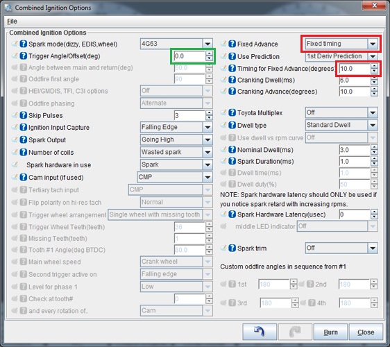
Navigate to the "Ignition Settings" tab and click on "Ignition Options/Wheel Decoder". If "Fixed Advance" is set to "Use Table", set it to "Fixed timing". This will tell the MSPNP to ignore the ignition table and hold a fixed advance angle. Set "Timing for Fixed Advance" to 10.0 degrees. Burn these changes.
-
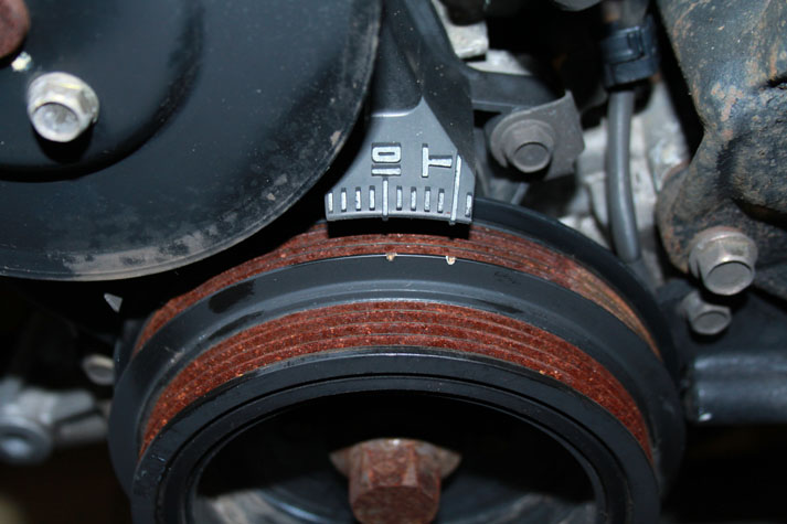
Use a timing light to confirm that you have 10 degrees of timing at the crank pulley. If you have a single mark on your crank pulley, align it with the "10" on the indicator dial. If you have two marks, align the left most mark will align with "10" on the indicator dial and the right mark will align with "T". If you have more timing, decrease the "Trigger Angle" (green box above). If you have less, increase this value.
-
Once the timing is set, click "Burn". Set "Fixed Advance" back to "Use Table". Burn again and close this menu. Cycle power to the MSPNP (turn the car off and back on). The MSPNP is now commanding timing advance based on the ignition table.
Removing the Vane Air Flow Meter
Since the MSPNP is speed density, you don't need to have the restrictive factory air flow meter in place. We've found gains of 3 to 5 horsepower by replacing the air flow meter with a length of straight pipe. This does require one wiring change, as there's an air temperature sensor in there. You'll need to substitute a GM IAT sensor with the air flow meter gone. This sensor connects to the first and sixth pins on the IAT connector, as shown in the graphic below. IAT sensors have no polarity, so it does not matter which wire you connect to which pin.
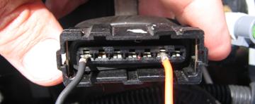
Simply wire a GM Open Element IAT Sensor into your factory wiring harness at the AFM connector. You can poke wires into the AFM connector, or you can cut and splice. Wire one lead of the GM Sensor to the first wire at the AFM Connector, and the other lead of the GM Sensor to the sixth wire at the AFM Connector. The wires should then be folded down over the edge of the AFM connector, and the whole assembly firmly and cleanly wrapped in high quality electrical tape sealing it up. 3M has tapes, such as Super88, that can handle the temps found in engine bays.
After installing the IAT, turn the ignition key on but do not start the engine. Connect to the MSPNP with TunerStudio. Go to the Tools menu and select Calibrate Thermistor Tables. Select Air Temperature Sensor. Select GM from the Common Sensor Values drop down box. Leave the bias resistor setting at 2490.0 ohms. Click Write to Controller. This will update the sensor calibration in the MSPNP.
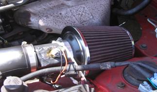
The IAT needs to be located where it will pick up the air temperature after anything in the intake that changes air temperature. So if you are using forced induction, it needs to be downstream of the turbo or supercharger and the intercooler. Here is a picture of an IAT sensor installed in a naturally aspirated car, with a cone filter taking the place of the stock airbox.
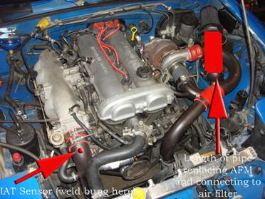
And here's a picture of one way to bypass your AFM and still get your air filter on there (using a popular turbo kit and charge pipe kit), and more importantly, it shows you exactly where to weld the IAT bung to measure air temp AFTER the turbo, and AFTER the IC. You need to know the air temp as it's entering the engine, nothing else will do us much good. If you are running forced induction this is critical, the stock IAT sensor in the AFM will not do.
Note: If you are using the MSPNP with a turbo or supercharger:
After you delete the AFM, install an IAT sensor in the location pictured above which is just before the throttle body inlet. The IAT needs to measure the air temperature as it's entering the engine, not the ambient air temperature in the engine bay as would be measured by the AFM. Only by placing the IAT just before the throttle body can an accurate air temperature measurement be taken AFTER the compressor has heated the air, and the intercooler has cooled it. Accurate air temps are needed for proper fueling and ignition advance calculations.
Installing an aftermarket Variable TPS
Though your vehicle did not come from the factory with a variable throttle position sensor, and a VTPS is not required for most of the features of the MegaSquirt EMS, the MSPNPP-MM9093 provides functionality to add a variable TPS using the factory wiring harness if you would like to. Some features do require a TPS reading, and it can also help with properly dialing in your acceleration enrichments (though your MSPNP by default will use the MAP signal for this, sometimes TPS based AE are easier to tune).
Here is the pinout to use if you wish to convert to a variable TPS.
| Function | ECU connector pin | TPS connector pin | Wire color |
| TPS signal | 4L | 1 | Green / White |
| Ground | 4C | 2 | Black / Green |
| 5 volt reference voltage | 1N | 3 | Red |
If you're not sure which connection on your TPS goes to which wire, check it with an ohmmeter/multimeter. Observe the resistance as the throttle opens and closes. Each pair of pins will behave differently:
-
The resistance between the 5 volt and ground pins will remain constant.
-
The resistance between the ground and signal pins will be low with the throttle closed and high with the throttle wide open.
-
The resistance between the 5 volt and signal pins will be high with the throttle closed and low with the throttle wide open.
Using these rules, you can establish which pin on the TPS goes to which wire. Note that we have not been able to find a TPS that plugs directly into the factory wiring and matches both the plug and the pinout, so you will need to do a bit of splicing to make this OPTIONAL modification.
Once you have the TPS installed, remove the top cover of the MSPNPPro. It's secured in place with 4 philips head screws. Locate the jumper labelled "VTPS Enable", also referred to as J4. Note, the silk screen printing may be somewhat obsured. Install a pull-off jumper in this location, then reinstall the top cover.
Connect to the MSPNP with the key on and the engine off. Go to the Tools menu and select Calibrate TPS. With your foot off the throttle, click the "Get Current" button next to the "Closed throttle ADC count" line. Then hold the accelerator to the floor and click the "Get Current" button next to the "Full throttle ADC count" line. The maximum reading is 1023 and the minimum reading is 0, but it's rare for a TPS to cover the entire range. It's more common to see the closed throttle reading in the 0 to 300 range and the full throttle in the 700 to 1000 range, but as long as the full throttle is more than the closed throttle by 200 counts or more, the TPS is functional. If the full throttle count is less than the closed throttle count, switch the ground and reference voltage wires. Once you have obtained adequate numbers, click the Accept button and it will save the values to the ECU.
Sequential Injection
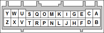
The MSPNPP-MM9093 is capable of sequential injection. '93 California models are already set up for this; all others must have their wiring harness repinned at the ECU to use this feature. If you choose not to wire the injectors into the rear option connector, you will need to wire up the injectors using this pinout for '90-'92 and '93 Federal models.
| Cylinder | ECU pin |
| 1 | 4U |
| 2 | 4V |
| 3 | 4Y |
| 4 | 4Z |
Furthermore, the following jumpers will need to be adjusted to match the following:
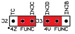
To enable sequential injection, go to the Basic/Load Settings -> Engine and Sequential Settings, and set Sequential On to "On." Click Burn, and turn the MSPNPP off and back on again.
Sensor Calibration
If you need to recalibrate your temperature sensors, such as after loading firmware, here are the values to use for the stock sensors. These work for both factory CLT and IAT sensors. GM IAT sensors can use the defaults in TunerStudio. The bias resistor value is 2490.
| Temperature (degrees F) | Temperature (degrees C) | Resistance (Ohms) |
| -4 | -20 | 16150 |
| 104 | 40 | 1150 |
| 176 | 80 | 330 |
Cooling Fan Control
Your MSPNP has the capability to use the PWM2 output for primary fan control, under Advanced Engine -> Prog. On/Off Outputs. The fan will come on whenever this output is on. Note that if the factory thermoswitch is plugged in, the thermoswitch can also activate the fan whether the MSPNP has commanded it to turn on or not, and vice versa - an "on" command from either the MSPNP or the thermoswitch will override an "off" command from the other. To allow automatic control of the fan, jumper J6 must be installed (see jumper listing below).
| Menu Location | Output Channel | Function | State | Condition (Default) |
| Basic Settings -> Fan Control | PWM2 (J6 must be set) | Primary Cooling Fan | On | CLT > 195 deg. F. |
| Startup/Idle -> Air Conditioning Idle-Up | Injector I | Secondary Cooling Fan | On | CLT > 200 deg. F. |
Auxillary Function I/O Configuration
Below is a listing of funcitons for auxillary I/O used from the MS3Pro module:
| I/O Point | Function |
| High Current 1 (HC1) | VVT |
| PWM2 | Fan 1 (J6 Must be set) |
| PWM3 | Alternator Field Control |
| Injector I (INJI) | Fan 2 |
| Injector J (INJJ) | AC Relay |
| Digital Frequency In 1 (DFIN1) | CEL |
| Digital Frequency In 2 (DFIN2) | VSS |
| Digital In 2 (DI2) | Clutch Signal |
| Digital In 3 (DI3) | AC Request |
Optional Configurations
Several jumpers are located on the lower, black circuit board inside the MSPNP. These are accessible by removing the top cover and are indicated as depicted below:

Default settings indicated in red.
J4: Variable TPS Enable
When this jumper is installed, it allows the use of a variable TPS.
This should be installed on 90-93 Miatas with a
modified TPS that generates a variable signal.
J5:
Tach Out on Connector J3, Pin 4I (1995.5+ Miata Only)
Unused
on this model.
J6: Cooling Fan Control (1.6L Miata Only)
When
this jumper is installed, the MSPNP will control the main cooling fan.
If this jumper is left off, the thermoswitch located on the thermostat
housing will automatically cycle the cooling fan.
J9: MAP Sensor Select
When this jumper is installed
in the default location, the internal 4-bar MAP sensor will be used.
If the jumper is moved to the location labelled "EXT", an external MAP
sensor wired into the rear option connector will be used. Iif an external
sensor is used, ensure that the scaling is properly set in TunerStudio (Tools -> Calibrate MAP/Baro).
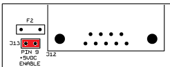
J13: 5VDC Supply on Pin 9 of Serial Connector
The MSPNP is capable of supplying 5VDC to pin 9 of the DB9 serial connector for use with external devices such as wireless Bluetooth adapters. The 5VDC supply is disabled by default. To enable the supply, you must remove the lid (4 screws) and place the jumper across the two pins labelled "J13" located near the serial connector at the corner of the PCB. Note that you will need a #1 philips or a "sharp" #2 philips to remove and replace the lid screws.
Rear Option Connector
An auxilliary connector and harness is provided to allow you to add functionality to your car. Below is the pinout of the rear connector.
| Pin | Function | Default Function | Notes |
| A | Sensor Ground | ||
| B | Knock Sensor | ||
| C | Analog Input 2 | ||
| D | Analog Input 1 | MAF | |
| E | IAT | ||
| F | External MAP Sensor | ||
| G | CANL | ||
| H | +5VRef | ||
| I | CANH | ||
| J | +12V Ignition | Maximum 0.5 Amps | |
| K | Digital Freq. In 3 | ||
| L | Digital Freq. In 2 | VSS | |
| M | Digital In 1 | Flex | |
| N | Digital In 2 | Clutch Signal | |
| O | Digital In 12V (DI4) | ||
| P | High Current 1 | VVT | |
| Q | High Current 3 | Nitrous | |
| R | High Current 2 | Boost Control | |
| S | Ignition D Logic Level | ||
| T | Injector H Logic Level | High Z or GPIO Only | |
| U | Ignition C Logic Level | ||
| V | Injector G Logic Level | High Z or GPIO Only | |
| W | Ignition B Logic Level | ||
| X | Injector F Logic Level | High Z or GPIO Only | |
| Y | Ignition A Logic Level | ||
| Z | Injector E Logic Level | High Z or GPIO Only |
Connector Pinouts for Engine Upgrades
It has become common to upgrade Miatas' engine to those from newer model years. The MSPNPPro has provisions to control all aspects of newer Miata engines including the alternator and VVT. Below is the connector pinout to assist you to assemble your own wiring harness to allow seamless integration of these newer engines.
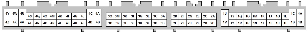
| Connector 1 (Factory Wiring) | |||
| N/C | 1A | 1B | +12V Ignition |
| Fuel Pump Relay (12V) | 1C | 1D | N/C |
| CEL (via DFIN1) | 1E | 1F | Tach Out |
| Cyl. 1/4 Ign. Coil (Ignition A Out) | 1G | 1H | Cyl. 2/3 Ign. Coil (Ignition B Out) |
| N/C | 1I | 1J | A/C Relay (Injector J Out) |
| N/C | 1K | 1L | Fan 1 Relay (PWM2) |
| VSS (DFIN2) | 1M | 1N | Throttle Switch 5V |
| N/C | 1O | 1P | N/C |
| A/C Switch In | 1Q | 1R | Fan 1 Relay (PWM2 via J6) |
| N/C | 1S | 1T | N/C |
| N/C | 1U | 1V | Clutch Switch (Digitial In 2) |
| Connector 2 (Optional Wiring) | |||
| CANH | 2A | 2B | Oxygen Sensor |
| CANL | 2C | 2D | Tach Out |
| External MAP Sensor | 2E | 2F | Knock Sensor |
| Ground | 2G | 2H | Digital In 1 (Flex) |
| PWM3 | 2I | 2J | Digital In 12V (DI4) |
| Analog In 2 | 2K | 2L | High Current 2 (Boost) |
| Connector 3 (Optional Wiring) | |||
| Ignition C (Cyl 4 Seq.) | 3A | 3B | Ignition D (Cyl 2 Seq.) |
| Ignition A (Cyl 1/4 WS, Cyl 1 Seq.) | 3C | 3D | Ignition B (Cyl 2/3 WS, Cyl 3 Seq.) |
| Injector C (Cyl 4 Seq.) | 3E | 3F | Injector D (Cyl 2 Seq.) |
| Injector A (Cyl 1/4 Batch, Cyl 1 Seq.) | 3G | 3H | Injector B (Cyl 2/3 Batch, Cyl 3 Seq.) |
| +12V Out (Relay Supply) | 3I | 3J | High Current 1 (VVT) |
| Sensor Ground | 3K | 3L | IAC |
| CKP (Crank) Signal | 3M | 3N | +5Vref |
| CMP (Cam) Signal | 3O | 3P | TPS |
| Connector 4 (Factory Wiring) | |||
| Ground | 4A | 4B | Ground |
| Sensor Ground | 4C | 4D | Sensor Ground |
| CKP (Crank) Signal | 4E | 4F | Sensor Ground |
| CMP (Cam) Signal | 4G | 4H | N/C |
| N/C | 4I | 4J | N/C |
| +5Vref | 4K | 4L | TPS |
| N/C | 4M | 4N | O2 Sensor |
| VAM Output (Ext MAP) | 4O | 4P | IAT Sensor |
| CLT Sensor | 4Q | 4R | N/C |
| Condensor Fan (Injector I Out) | 4S | 4T | Fuel Pump Relay (Unused on 90-93) |
| Injector A | 4U | 4V | Injector B (Injector D - 93 CA Emis) |
| IAC (PWM1) | 4W | 4X | N/C |
| N/C (Injector B - 93 CA Emis) | 4Y | 4Z | N/C (Injector C - 93 CA Emis) |
10-5-21 - 1.4

