MegaSquirt PNP Pro Documentation
Model/Vehicle specific installation guide for model MSPNPP-JZ9298 for a 1993-1998 Toyota Supra Turbo (2JZ-GTE) and 1993-1997 Toyota Supra Non-Turbo (2JZ-GE).
Please read all documentation before installing your MegaSquirtPNP EMS and verify that you've followed all steps before starting your engine for the first time.
Physical Installation
All you'll need for a successful installation are some basic hand tools. Some drilling of the original bracketry is required.
For a thorough and professional installation, you will need the following items:
-
10mm socket and ratchet
-
Electric Drill
-
3/8" Drill Bit
-
Diagonal Wire Cutters
-
Zip Ties
-
Timing Light
-
Laptop with Tuner Studio installed
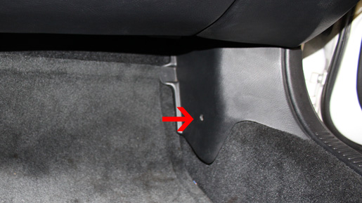
The stock ECU is located in the passenger's side foot well, beneath the carpet. To gain access to the ECU, you must first remove floor mat followed by the kick panel. The kick panel is secured in place with a push-pin located in the center. Remove the pushpin and the kick panel should pull away.
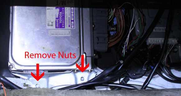
With the kick panel out of the way, the carpet can be pulled back reveal the ECU and the TRC (traction control computer). The ECU is the larger, left most unit on the USDM cars and is held in place by two nuts at its bottom and a slip connector at the top. Remove the two nuts and slip the ECU down. It should come free at this point.
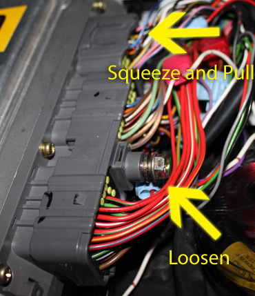
Disconnect the wiring harness from the ECU by loosening the large bolt at the center of the bottom connector counter clockwise. If the connector doesn't easily pull free, the bolt isn't completely disengaged. Once the bottom connector is disconnected, remove the top connector by squeezing the release tabs on both side, while pulling on the housing. Avoid pulling on the wiring as this can damage the connector.
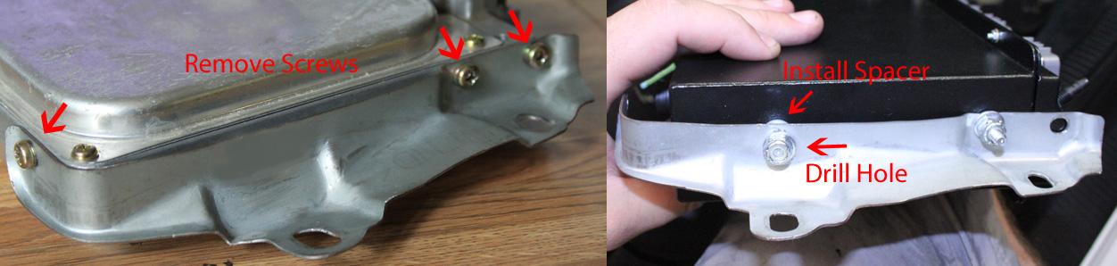
With the OE ECU free from the vehicle, remove both upper and lower brackets from its housing as they will be reused to install the MSPNP. Assemble the upper bracket to the MSPNP as shown below and secure with the nut provided. Note the orientation of the main harness connector on the face of the MSPNP.
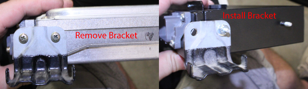
The lower bracket will require the addition of one hole to be drilled so that it can be installed properly. As shown below, align the rear most, forward hole of the bracket with forward most stud on the side of the ECU. Mark the location where the rear stud aligns on the bracket and using a 3/8" drill bit, drill a hole at that mark. Before installing the bracket, slide the included spacer over the rear stud of the ECU. Install the bracket and secure with the nuts provided. The end result should resemble the following picture:
At this time, the main harness can be connected to the MSPNP. Press the single connector firmly into place until its latches click in. Press the double connector in place. To ensure that the center bolt isn't cross threaded, run it in a few threads by hand. If it doesn't bind, tighten the center bolt completely, while ensuring that it isn't over tightened.
Connect the USB cable to the ECU and route it to a location of your choosing. The glove box is a fairly typical location for the free end of the cable.
Vacuum Line Routing
Before securing the ECU to the car, a vacuum line must be run from the engine bay. While there are several ways this can be accomplished, one method is depicted below.
Beginning at the intake manifold, a nipple just forward of the idle valve provides a perfect source for a vacuum reference. Using the included tee and vacuum line, remove the hose that is attached to this nipple and tee into the source as shown below.
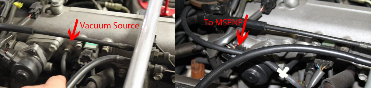
Route the hose toward and across the firewall to the driver's side corner. While routing, ensure that the hose is secured away from moving objects such as the throttle cable.
Secure the hose in place within the engine bay snuggly with zip ties. Ensure that the ties are not pulled too tightly so that they don't pinch the hose closed.
The hose will route into the fender area and through a grommet in the firewall there. Access to this area will require removal of the front driver's side wheel as well as the wheel liner. To begin, reference the vehicle's owner's manual regarding the proper procedure to raise the car and remove the wheel.. For your safety, it is advised that the car be secured with jack stands once raised.
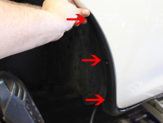
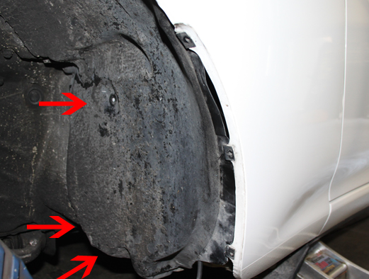
The fender liner is secured between a rock guard and the fender and held in place by three screws. There are three additional screws that secure the fender liner to the chassis. Remove these and pull the liner back to expose the wiring harness grommets through which the vacuum hose will pass.
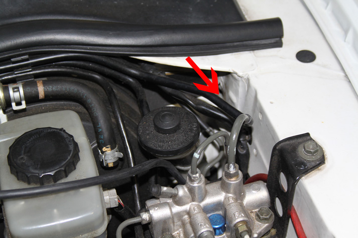
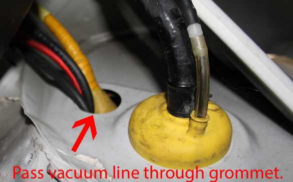
There are two large rubber grommets in the firewall on the driver's side corner of the engine bay. CAREFULLY make a slit or hole large enough to pass the vacuum line through. If you use a knife, use extreme caution as there are many wires in this area that you certainly don't want to damage. NOTE: The below image depicts a temporary install. You should not pass the vacuum hose between the sheet metal and the grommet as the hose will become pinched and operation of the MSPNP will be negatively affected.
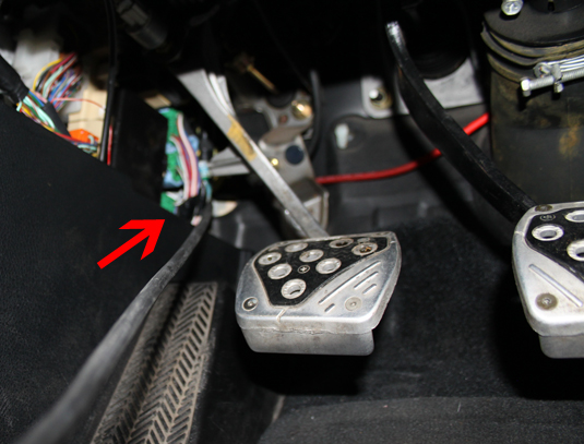
The vacuum line will enter the passenger compartment near the clutch pedal.
Once the vacuum line is brought into the passenger it must be routed to the ECU. Using care, pass the hose through the dashboard to the location of the ECU. Be careful to keep the hose away from moving parts such as the pedals, steering column, and climate controls. Secure the hose in place using zip ties, but don't pull them so tight as to pinch the hose. Connect the hose to the nipple on the MSPNP.
The MSPNP can now be bolted into place of the original ECU using the original hardware in the original location. Reassembly, including the fender liner, wheel, floor carpet, and kick panel, of the car can be completed now.
Verifying and Adjusting Base Timing
Because the factory ECU is no longer in control of ignition timing, it will be necessary to make checks to ensure the MSPNP is accurately delivering the proper timing. Improper ignition advance can cause engine damage if improperly set or is left unchecked.
The MSPNP will have a base ignition map loaded and ready to use. However, it is necessary to ensure that the timing advance being commanded by the MegaSquirt is in sync with what the engine is actually receiving. These steps will require the use of a timing light and a laptop with a copy of Tuner Studio running.
-
Connect a timing light on the cylinder #1 spark plug wire. Use all due caution here, as secondary ignition voltage can be as high as 100,000 volts or more. Also ensure that the timing light's cords can not get tangled in moving engine parts or burned on hot components.
-
Make sure your tuning laptop is connected to your MSPNP and start your vehicle. If you have not already done so, start Tuner Studio MS or Tuner Studio Lite. Make sure that your laptop connects to the MSPNP and you are online.
-
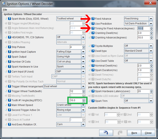
Navigate to the "Ignition Settings" tab and click on "Ignition Options/Wheel Decoder". If "Fixed Advance" is set to "Use Table", set it to "Fixed timing". This will tell the MSPNP to ignore the ignition table and hold a fixed advance angle. Set "Timing for Fixed Advance" to 10.0 degrees. Burn these changes.
-
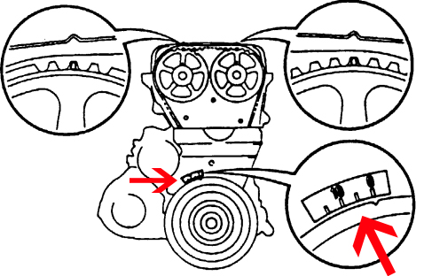
Use a timing light to confirm that you have 10 degrees of timing at the crank pulley -- the dimple on the crank pulley will align with "10" on the indicator dial . If you have more timing, decrease the "Tooth #1 Angle" (green box above). If you have less, increase this value.
-
Once the timing is set, click "Burn". Set "Fixed Advance" back to "Use Table". Burn again and close this menu. Cycle power to the MSPNP (turn the car off and back on). The MSPNP is now commanding timing advance based on the ignition table.
Removing the Mass Air Flow Meter
If you choose to use the MSPNP in Speed Density mode (MAP Sensor), air flow meter is no longer needed. While not necessary, it is recommended to remove the AFM for a small performance increase. At the very least, the air meter should be unplugged and the connector neatly tied away.
If, however, you choose to use the included base map whereby the air meter is used, you will certainly not want to remove this sensor.
Sensor Calibration
If you need to recalibrate your temperature sensors, such as after loading firmware, here are the values to use for the stock sensors. These work for both factory CLT and IAT sensors. GM IAT sensors can use the defaults in TunerStudio. The bias resistor value is 2490.
| Temperature (degrees F) | Temperature (degrees C) | Resistance (Ohms) |
| -4 | -20 | 15000 |
| 104 | 40 | 1000 |
| 176 | 80 | 300 |
Sequential Turbocharger Control
The MSPNP is configured to operate the sequential turbocharger assembly in a strategy similar to that of the original configuration using three I/O points (see tables below). If you choose to convert your car to a single turbocharger, two I/O points then are freed for use as general purpose I/O. Continue to use "High Current 2" (HC2) for standard wastegate boost control.
Fuel Pump Control
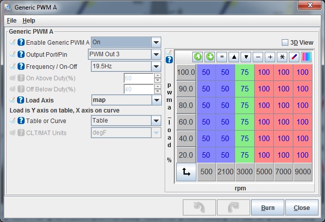
In stock trim, the fuel pump is operated by a separate controller from the ECU. This controller accepts a 5-volt PWM signal from the ECU and varies the pump speed as dictated by the PWM duty cycle. The duty cycle is defined in the "Generic PWM A" table found under the "Advanced Engine" menu.
In some applications, especially those where high power is generated and/or an aftermarket fuel pump is used, it will be desired to control the fuel pump directly with a relay (not included). The following steps will guide you in implementing this solution. It is highly recommended that an appropriately sized fuse be installed in-line with the fuel pump and relay.
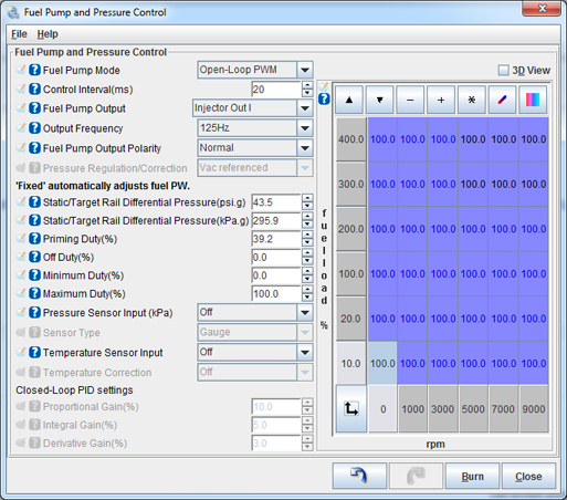
- Open TunerStudio, navigate to the "Fuel Settings"
menu, select "Fuel Pump and Pressure Control",
set "Fuel Pump Mode" to " Open-Loop PWM",
"Fuel Pump Output" to "Injector Out I", and set all
cells to 100. All other settings can be ignored.
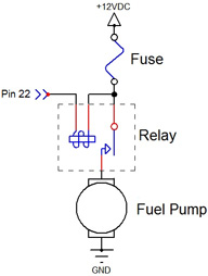
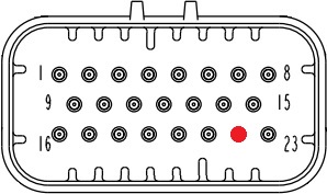
- Using the schematic below, wire the fuel pump relay to pin 22 on the
rear option connector.
Auxiliary Function I/O Configuration
Below is a listing of functions for auxiliary I/O used from the MS3Pro module:
| I/O Point | Function |
| HC2 | Waste Gate VSV (Boost Control) |
| PWM1 | VSV for Exhaust Bypass Valve |
| PWM2 | VSV for Exhaust Gas Control Valve |
| PWM3 | Fuel Pump Speed |
| Injector J (INJJ) | AC Relay |
| Digital Frequency In 1 (DFIN1) | CEL |
| Digital Frequency In 2 (DFIN2) | Driveline Speed 1 |
| Digital Frequency In 3 (DFIN3) | Driveline Speed 2 |
| Digital In 3 (DI3) | AC Request |
| Analog In 1 (DI1) | Mass Air Flow Sensor (MAF) |
Optional Configurations
Several jumpers are located on the lower, black circuit board inside the MSPNP. These are accessible by removing the PCB assembly and are indicated as depicted below:
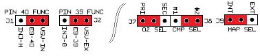
Default settings indicated in red.
Sets the functionality of pin E9-40 on the main connector. In the default location, the pin is connected to Injector G of the MSPNPPro Module and controlls the intake air control valve VSV on the 2JZ-GTE. In the secondary location, this pin is connected to Injector H of the MSPNPPro Module.
J1: Pin E9-39 Function
Sets the functionality of pin E9-39 on the main connector. In the default location, the pin is connected to PWM2 of the MSPNPPro Module and controls the exhaust bypass VSV on the 2JZ-GTE and the the ACIS VSV on the 2JZ-GE. In the secondary location, this pin is connected to Injector G of the MSPNPPro Module.
J8: Cam Sensor Select
Sets which cam sensor is to be be used. The default position connects the rear sensor. Moving the jumper will allow use of the front sensor.
J9: MAP Sensor Select
When this jumper is installed in the default location, the internal 4-bar MAP sensor will be referenced. If the jumper is moved to the location labelled "EXT", the OE MAP sensor is referenced. If it is desired to wire in your own MAP sensor to the rear option connector, remove this jumper completely. If an external sensor is used, ensure that the scaling is properly set in TunerStudio (Tools -> Calibrate MAP/Baro). The MSPNP calibration is, by default, set to that of the internal MAP sensor.
Rear Option Connector
An auxilliary connector and harness is provided to allow you to add functionality to your car. Below is the pinout of the rear connector.

| Pin | Function | Default Function | Notes |
| 1 | Digital In 1 | Flex Fuel | |
| 2 | Digital Frequency In 2 | Drive Line Speed 1 | After 4/10/15 |
| 3 | +5VRef | ||
| 4 | Sensor Ground | ||
| 5 | High Current 2 | Waste Gate VSV | Boost Control |
| 6 | High Current 3 | Nitrous | |
| 7 | Injector G | ||
| 8 | Injector H | ||
| 9 | CANH | ||
| 10 | CANL | ||
| 11 | High Current 1 | ||
| 12 | External MAP Sensor | ||
| 13 | O2 Sensor | ||
| 14 | Analog In 2 | ||
| 15 | IAT | ||
| 16 | Ignition A Logic Level | 2JZ-GE Seq. Ignition | |
| 17 | Ignition B Logic Level | 2JZ-GE Seq. Ignition | |
| 18 | Ignition C Logic Level | 2JZ-GE Seq. Ignition | |
| 19 | Ignition D Logic Level | 2JZ-GE Seq. Ignition | |
| 20 | Ignition E Logic Level | 2JZ-GE Seq. Ignition | |
| 21 | Ignition F Logic Level | 2JZ-GE Seq. Ignition | |
| 22 | Injector I Logic Level | High Z, Fuel Pump, or GPIO Only | |
| 23 | Injector J Logic Level | AC Relay | High Z or GPIO Only |
TRAC Warning Light
Please note that the MSPNP does not include integration with the OE traction control system (TRAC). Therefore, the fault indicator on the dahsboard will illuminate and/or flash.
7-24-19 - 1.1

