MSPNP Pro Documentation
Model/Vehicle specific installation guide for model MSPNPP-GNX8487 for a 1984-1987 Buick Regal Grand National.
Please read all documentation before installing your MSPNP EMS and verify that you've followed all steps before starting your engine for the first time.
Physical Installation
All you'll need for a successful installation are some basic hand tools. No cutting or drilling of the original sheet metal or bracketry is required.
For a thorough and professional installation, you will need the following items:
-
Ratchet
-
8mm socket
-
Small Slotted Screw Driver
-
#2 Phillips Screw Driver
-
Small Needle Nose Pliers
-
Sharp Awl or Small Knife
-
Zip Ties
-
Laptop with TunerStudio installed
-
Disconnect the negative battery cable.
-
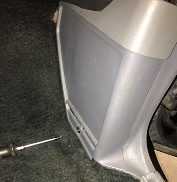
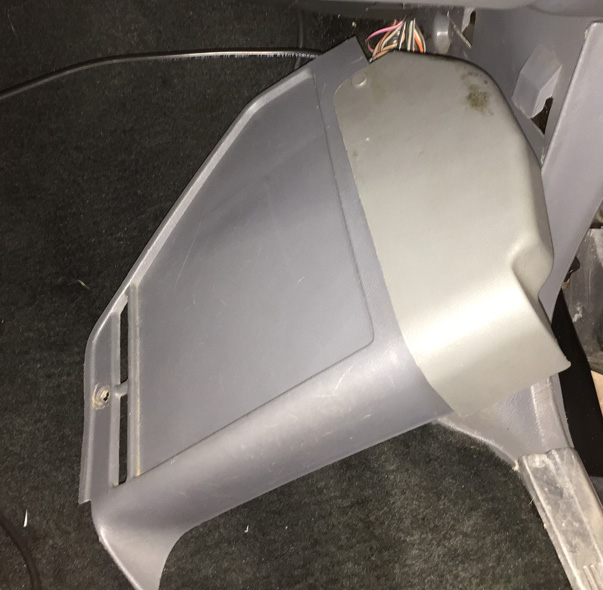
The stock ECU is located within a pocket in the kick panel of the passenger side footwell. A single Philips head screw secures this panel in place. Remove this screw and pull the panel out and away.
-
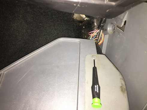
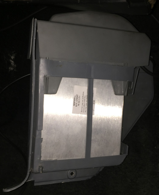
Remove the wire cover from the top pocket by removing a single plastic push rivet.
-
Slide the ECU from the pocket.
-
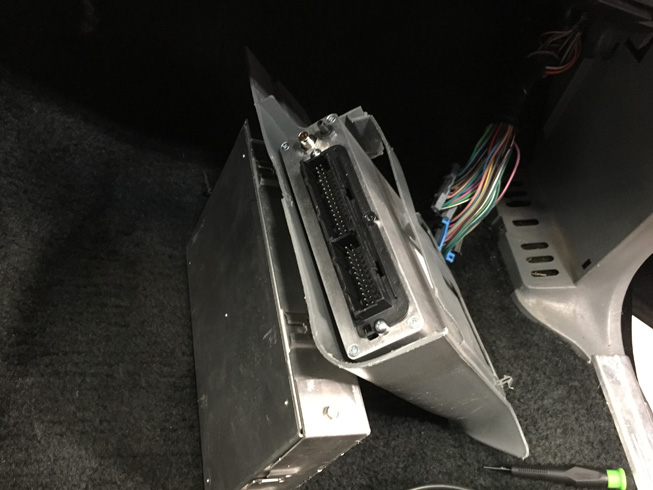
Disconnect the wiring harness from the ECU.
Older models use metal clips to secure the harness connectors to the ECU connector. Disengage the metal retention clips on the connectors with a small pry tool and gently pull the connector outward.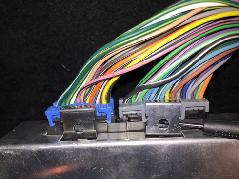
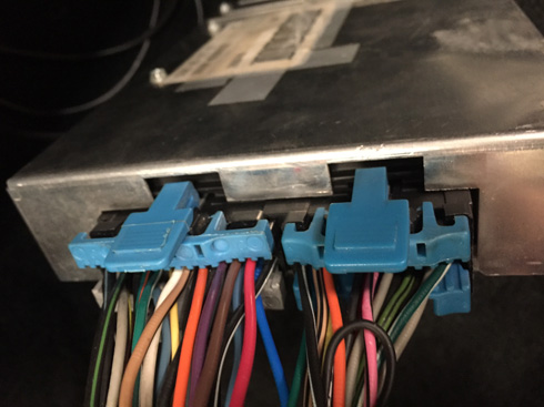
Newer models use plastic thumb clips to secure the harness connectors to the ECU connector. Disengage the plastic thumb clips on the connectors by pressing the lever and gently pull the connector outward.
-
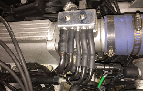
The vacuum/boost reference can be sourced from either the OE MAP sensor hose or at the manifold behind the throttle body. Cut the selected vacuum line and insert the tee in line (if necessary).
-
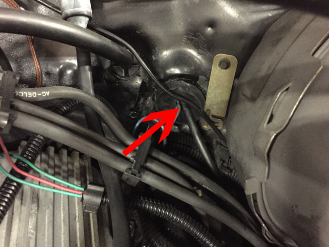
There is a hole just behind the driver's side valve cover that makes a great point for routing the vacuum line. Pierce the plug that is found in this hole with a sharp awl or small knife. Exercise care as to not damage anything behind this plug. Pass the vacuum hose through the piercing and use of a coat hanger or other stiff wire will facilitate passage of the hose through the interior sound deadening insulation.
-
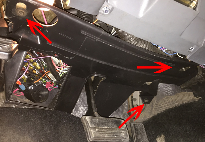
Remove the plastic panel from beneath the steering column inside the passenger compartment to gain access to the hole in the firewall. The panel is held in place by three 8mm screws.
-
Locate the hose that was passed through the rubber plug in the firewall and pull a sufficient length through. Neatly route the hose behind the dashboard to the location of the ECU while being careful to avoid moving objects (i.e. throttle pedal).
-
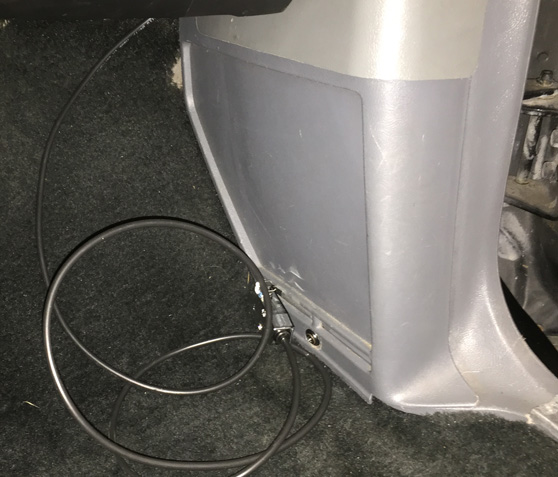
Neatly route the vacuum hose through the engine bay to the previously installed vacuum tee. Be sure to avoid hot or moving objects to avoid damaging the hose. Secure the hose with zip ties, but don't pull the ties so tight as to pinch the hose closed. Trim the hose to an appropriate length and connect it to the tee or other chosen vacuum reference. Two suggested routes can be found below:
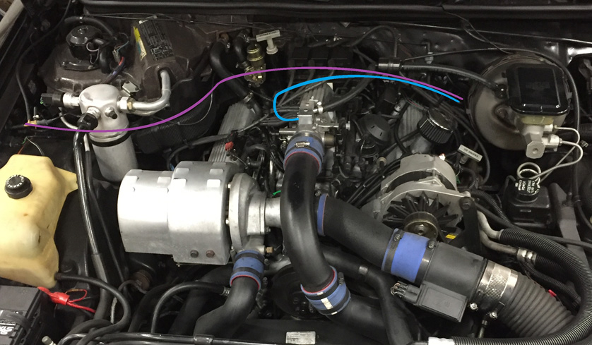
Hose routing suggestions. -
Insert the MSPNP ECU into the ECU pocket so that when it is installed, the serial connector will be toward the firewall.
-
Connect the supplied serial cable and the vacuum hose to the MSPNP. Note that the connector is keyed and, when properly aligned, will easily seat onto the pins. Once seated, tighten the ferrule clockwise.
-
Connect the OEM wiring harness to the MSPNP ensuring the connectors are firmly seated and latched into place.
-
Reinstall the wire cover onto the pocket and insert the plastic push rivet.
-
Fit the kick panel back into place and secure with the previously removed screw.
-
Route the free end of the serial cable to the desired location.
-
Reinstall the plastic panel beneath the steering column and secure the three previously removed screws.
-
Reconnect the negative battery cable.
-
At this point, power up, testing, and tuning of the MSPNP can begin.
Removing the Mass Air Flow Meter
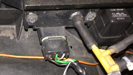
Since the MSPNP calculates engine load using a MAP sensor, the air flow meter is no longer needed. While not necessary, it is recommended to remove the AFM for a performance increase. At the very least, the air meter should be unplugged and the connector neatly tied away.
Wideband Sensor Addition
If a wideband Oxygen sensor is to be installed, its signal can be wired to either Analog Input 1, or the original O2 sensor wiring in the OE harness.
Sensor Calibration
If you need to recalibrate your temperature sensors, such as after loading firmware, below are the values to use for the stock sensors. The bias resistor value is 2490.
| Temperature (degrees F) | Temperature (degrees C) | Resistance (Ohms) |
| Coolant Temperature Sensor (CLT) | ||
| -40 | -40 | 100700 |
| 86 | 30 | 2238 |
| 210 | 99 | 177 |
| Intake Temperature Sensor (IAT) | ||
| -40 | -40 | 100700 |
| 86 | 30 | 2238 |
| 210 | 99 | 177 |
Auxiliary Function I/O Configuration
Below is a listing of specifically purposed functions for auxiliary I/O used on the MS3Pro module:
| I/O Point | Function |
| High Current 1 (HC1) | AC Clutch |
| PWM2 | Cooling Fan |
| PWM3 | Torque Converter Lockup |
| Digital Frequency In 1 (DFIN1) | CEL |
| Digital Frequency In 2 (DFIN2) | VSS |
| Digital In 2 (DI2) | Neutral Switch |
| Digital In 3 (DI3) | AC Request |
| Analog Input 2 (AI2) | Gear 1/2, 3, 4 Detection |
Optional Configurations
Two configuration jumpers are located on the lower, black circuit board inside the MSPNP. It is accessible by removing the top cover and is indicated as depicted below:
J5: Gear 2/3 Selection
Analog input 2 is assigned to detect the status of gears 2 and 3 by default. If desired, this can be disabled by removing the jumper at J5 and AI2 can then be repurposed as a spare analog input via the rear option connector. Note, access to this jumper will require the removal of the main ECU module from the lower board.
J6: Map Sensor Selection
The MSPNP has a built in MAP sensor, but you have the option of using either the original external OEM sensor that is under the hood. Depending on your selection, J6 should be configured to match. Furthermore, if an external sensor is used, ensure that the scaling is properly set in TunerStudio (Tools -> Calibrate MAP/Baro).
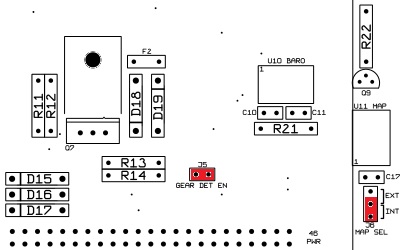
Default Selection in Red
Rear Option Connector
An auxilliary connector and harness is provided to allow you to add functionality to your car. Below is the pinout of the rear connector.
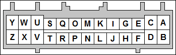
| Pin | Function | Default Function | Notes |
| A | Analog Input 2 | Gear 1/2, 3, 4 Detection | |
| B | Knock Sensor | ||
| C | DFIN3 | ||
| D | Analog Input 1 | Optional Wide Band O2 Sensor | |
| E | Digital Input 1 | Optional Flex Fuel | |
| F | CMP+ | ||
| G | CANL | ||
| H | 5V Vref | ||
| I | CANH | ||
| J | Sensor Return | ||
| K | Injector J | General Purpose Output or Hi-Z Only | |
| L | High Current 3 | ||
| M | Injector I | General Purpose Output or Hi-Z Only | |
| N | High Current 2 | ||
| O | Injector H | General Purpose Output or Hi-Z Only | |
| P | Spark H | ||
| Q | Injector G | General Purpose Output or Hi-Z Only | |
| R | Spark G | ||
| S | Injector F | Hi or Low-Z | |
| T | Spark F | ||
| U | Injector E | Hi or Low-Z | |
| V | Spark E | ||
| W | Injector D | Hi or Low-Z | |
| X | Spark D | ||
| Y | Injector C | Hi or Low-Z | |
| Z | Spark C |
7-24-19 - 1.1

