MSPNP Pro Documentation
Model/Vehicle specific installation guide for model MSPNPP-E369395 for a 1993-1995 BMW 325i, 328i, and M3.
Please read all documentation before installing your MSPNP EMS and verify that you've followed all steps before starting your engine for the first time.
Physical Installation
All you'll need for a successful installation are some basic hand tools. No cutting or drilling of the original sheet metal or bracketry is required.
For a thorough and professional installation, you will need the following items:
-
Ratchet
-
7mm, 10mm, and 13mm sockets
-
Small Slotted Screw Driver
-
#2 Phillips Screw Driver
-
Small Needle Nose Pliers
-
Zip Ties
-
Laptop with TunerStudio installed
-
Disconnect the negative battery cable.
-
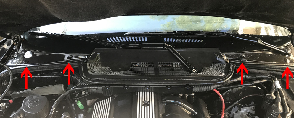
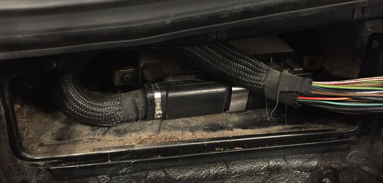
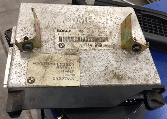
The stock ECU is located behind a cover inside the passenger's side firewall, accessible from within the engine bay. The cover is hidden behind a piece of rubber insulation that is secured by three push locks and two plastic nuts.
-
To remove the insulation, use a 10mm socket to remove the nuts. Then, use a small slotted screwdriver to pop out the center locks of each of the three clips.
-
Pull the insulation away to expose the ECU cover. Care should be used as this insulation may be dry-rotted and/or brittle from heat and age.
-
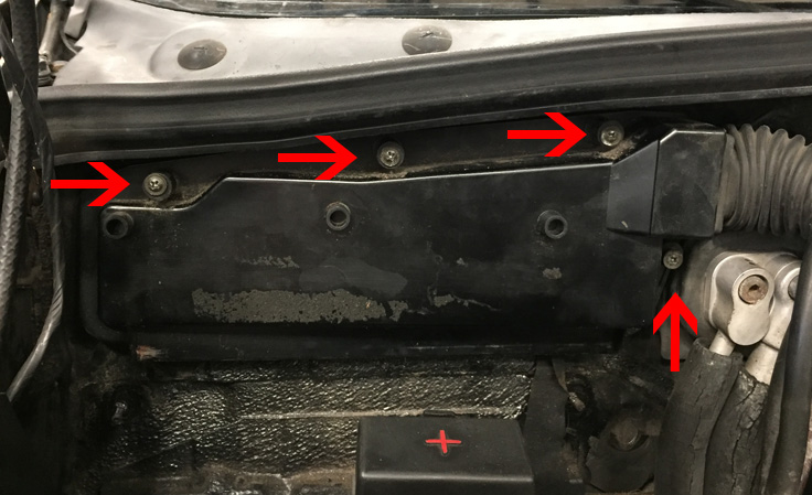
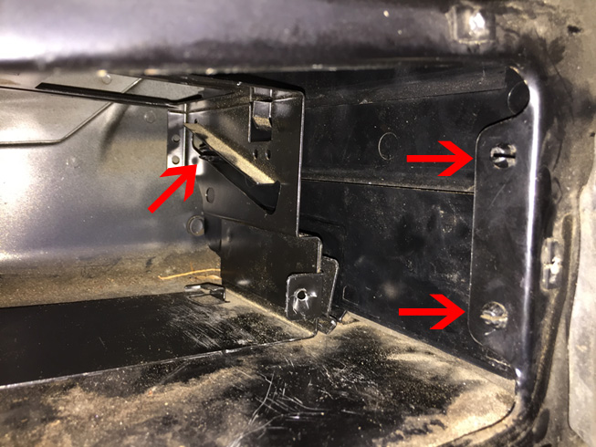
The ECU cover is secured by 4 Phillips head screws. Remove these screws and pull the cover away.
-
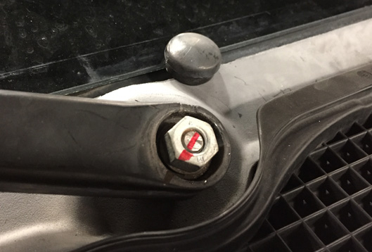
On 2-door hard top models, both windshield wiper arms must be removed. To remove the wiper arms, begin by carefully prying off the dress cover from the pivot nut. Place a mark across the post and arm so that it can be properly realigned during reassembly. Remove the 13mm nut and pull the wiper arm away from its post. Both arms are removed in the same fashion.
-
On 2-door hard top models, remove the cowl cover by removing the four plastic retaining screws. The entire cover can then be removed.
-
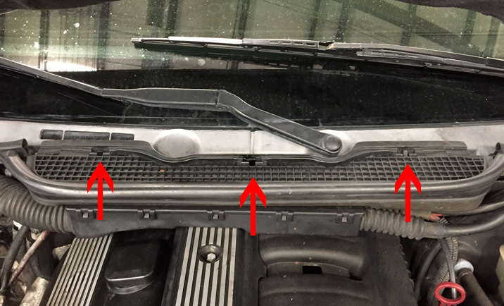
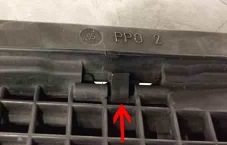
On 4-door and convertible models, remove the upper center cowl cover by squeezing each of the 3 retainer clips towards the windshield, one at a time, while simultaneously pulling up on the cover. Once the three clips are freed, lift and remove the upper cowl cover along with its associated rubber weather strip.
-
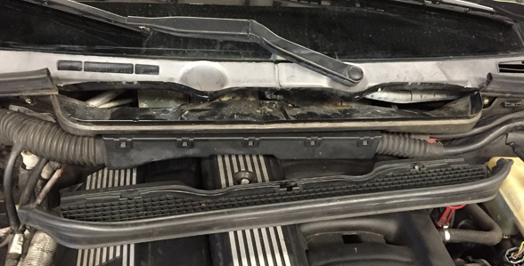
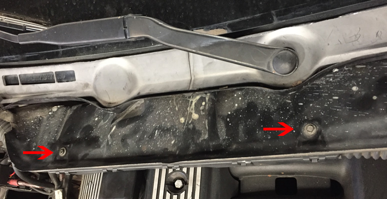
A wiring harness conduit is secured to the lower cowl with two 7mm screws. Remove these screws.
-
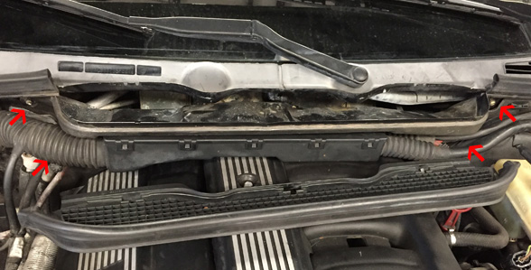
The lower cowl cover is secured by 4 Phillips head screws. Remove the 4 screws and pull the lower cowl cover upward and away from the firewall noting that it may be secured in some places with adhesive. The wiring conduit will rest on top of the engine.
-
Remove the oil cap and cover the port with a protective covering such as tape to prevent screws and/or tools from falling into the engine.
-
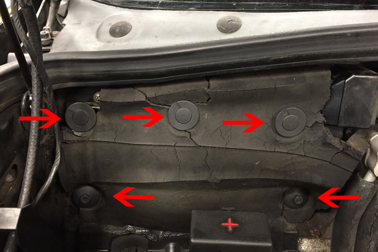
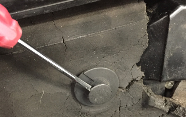
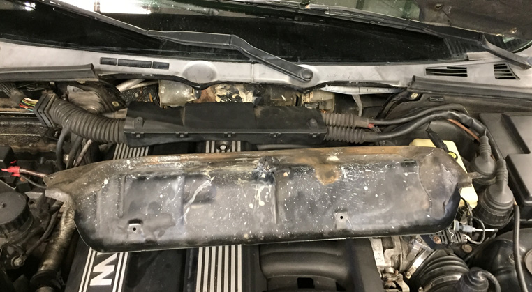
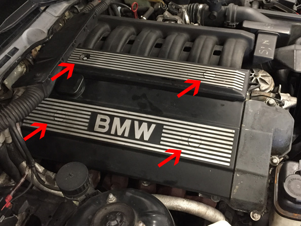
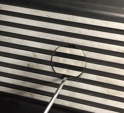
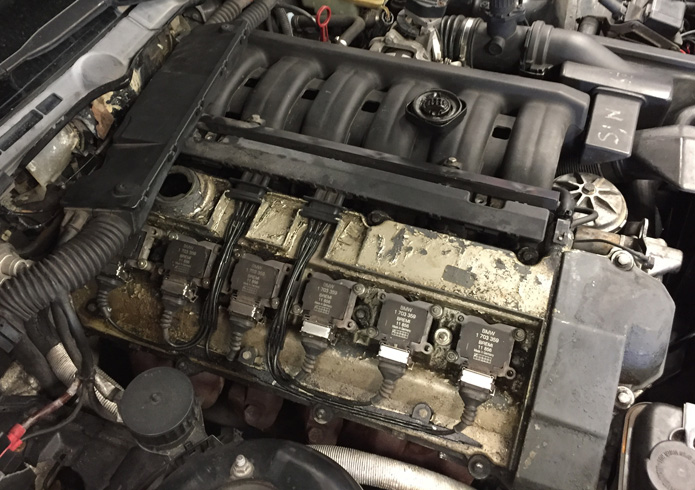
Two plastic engine covers will need to be removed from the engine. These are secured in place by two screws that are concealed behind plastic caps. To begin removal, gently pry the plastic caps away with a small slotted screwdriver. Remove each of the 10mm nuts that secure the covers, then pull the covers away from the engine.
-
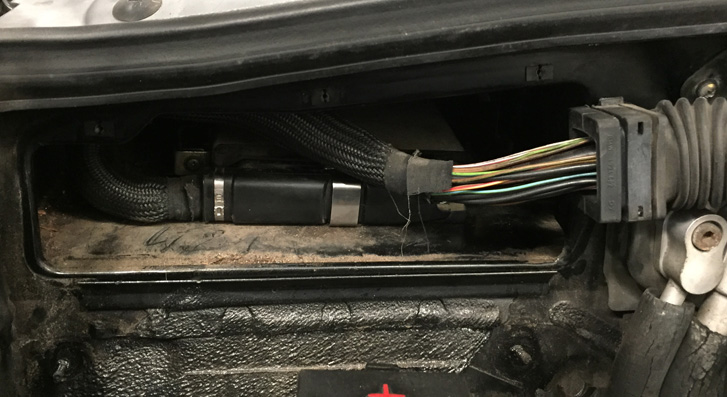
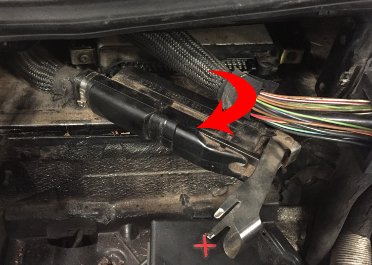
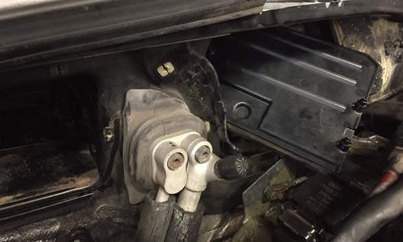
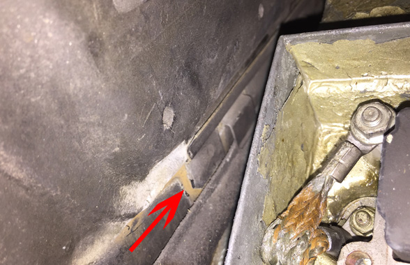
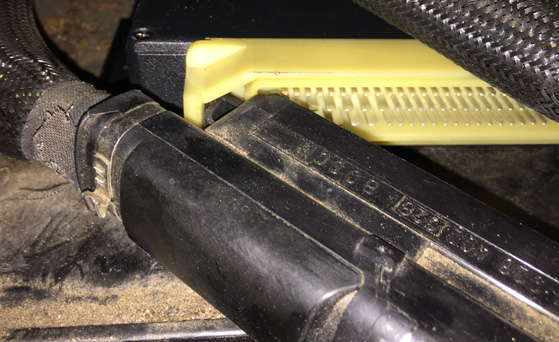
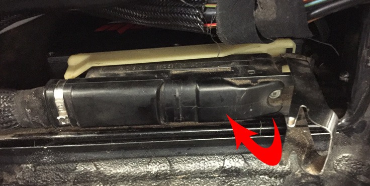
Disconnect the engine harness from the OEM ECU by first pulling the silver locking tab toward you and rotating it toward the driver's side of the car. Once the locking tab is fully extended, pull it to unseat the main connector from the ECU. Finally, pull the connector and harness away from the ECU.
-
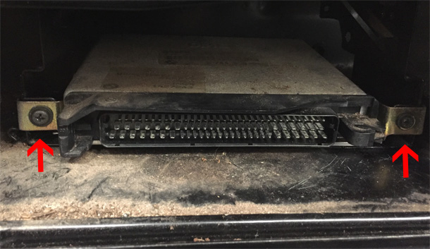
The OEM ECU is held into its carrier with a pair of clips secured by a Philips head screw in each. Remove these screws and pull the ECU straight out of its carrier.
-
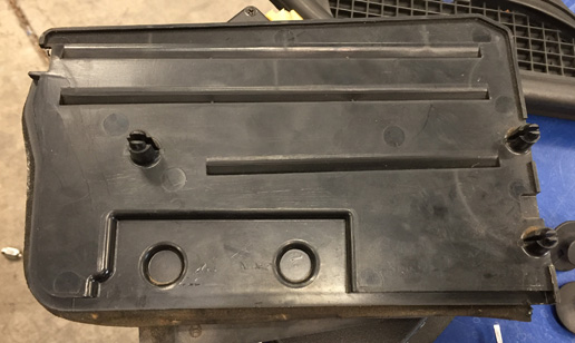
A divider plate exists between the ECU compartment and the main cowl area. It is secured in place by three squeeze pins. Release these three pins by squeezing them with a pair of needle nose pliers and simultaneously pushing toward the centerline of the car. Remove the divider through the main cowl opening. Note that articulation will be required to move it around and over the air conditioning lines (if present).
-
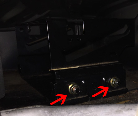
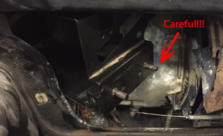
The ECU carrier is secured by a clip held in place by two 10mm nuts. Completely remove these two nuts and the small bracket that secures the carrier.
-
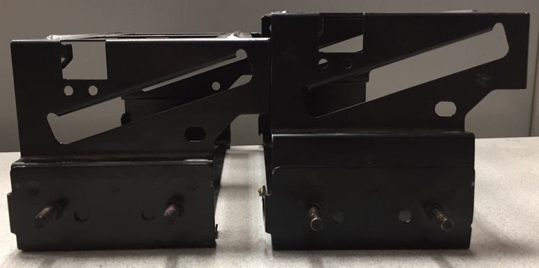
NOTE: Removal of the carrier is the most difficult step in this installation and patience must be exercised as to not damage the air conditioning lines or blower ducting. Furthermore, two variants of the ECU carrier were used by BMW, one being about a half inch taller than the other. Both can be removed in the same fashion, but the taller variant is a much tighter fit. It may be easier to slightly compress the carrier into a trapezoidal form to reduce its height or slightly bend the passenger's side edge of the firewall outward.
-
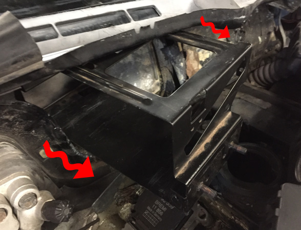
With the carrier free to move in the cowl, carefully work it over the air conditioner lines and partially into the main cowl opening.
-
Slightly compress the blower inlet ducting to allow passage of the ECU carrier.
-
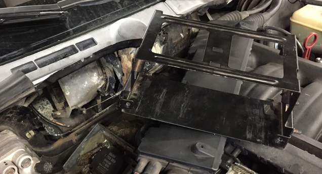
Continue to gently work the carrier through the cowl opening and over top of the engine's oil fill port until it can be completely removed.
-
-
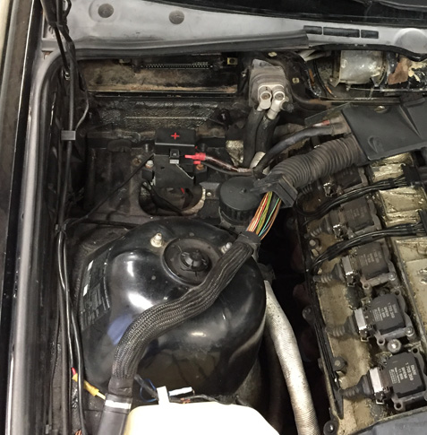
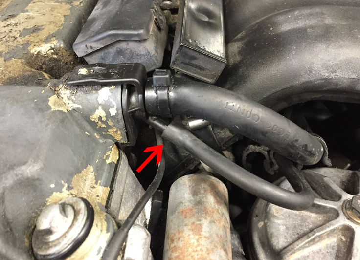
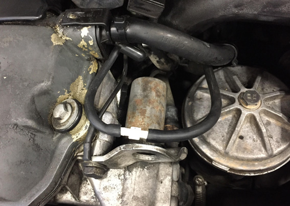
Disconnect the small hose from the PCV valve that is located on the forward side of the rocker cover. Install a rubber cap on the PCV valve.
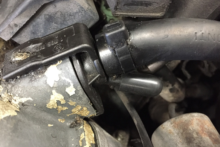
-
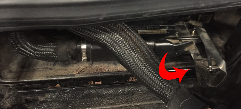
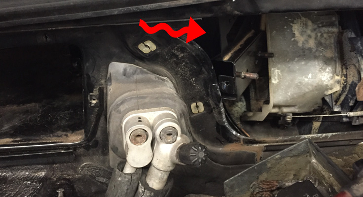
Route the supplied vacuum hose as depicted below.
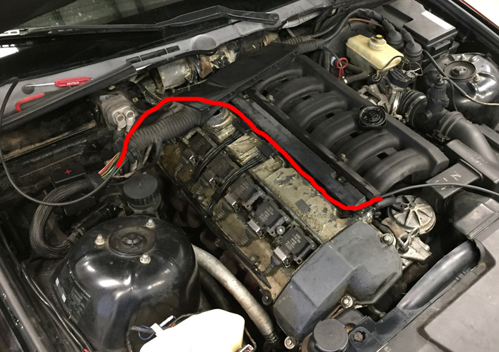
-
Cut a small slot in the wiring conduit bellows close to where the wires exit into the ECU compartment. Insert the vacuum hose into the hole that was just made and pull about 18" of hose through.
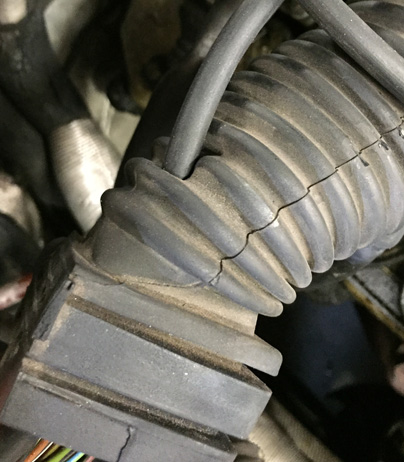
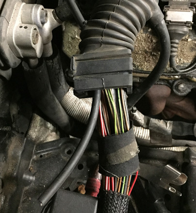
-
OPTIONAL STEP: If desired, a hole may be drilled into the ECU cowl compartment to allow passage of the tuning cable into the passenger compartment. This procedure will be left to the user to determine as it is (1) optional, and (2) may require removal of the dashboard, HVAC ducting, and/or airbag. AMPEFI and DIYAutoTune recommend handling and removal of airbag modules be left to professional services.
-
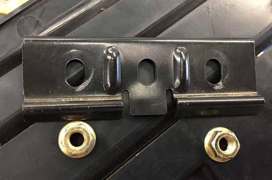
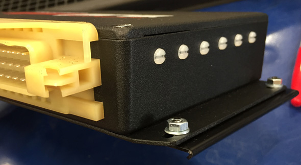
Loosely assemble the supplied retaining brackets to the MSPNP flanges with the provided nuts.
-
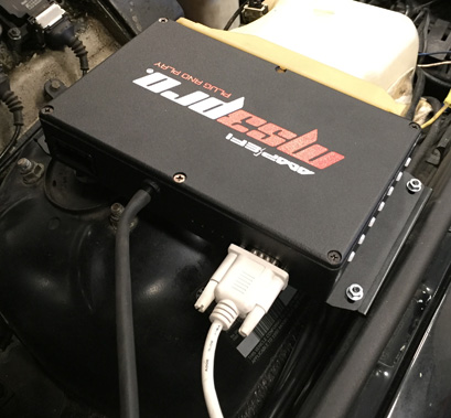
Attach the end of the vacuum hose that was previously routed through the conduit to the barbed nipple at the back of the MSPNP. Additionally, connect the supplied serial cable and secure the thumb screws. If wiring is to be connected to the options connector, install this wiring and insert the connector into the MSPNP at this time.
-
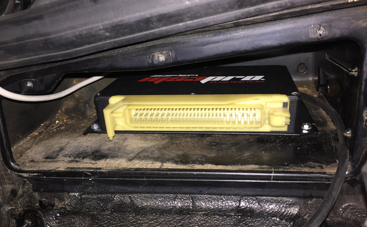
Insert the MSPNP into the ECU compartment so that the rear wiring and hose just come into contact with the back wall of the compartment. Engage its mounting flanges with the cleats in the bottom of the compartment. Tighten the four nuts and ensure that the MSPNP is securely seated.
-
Reinstall the divider plate. Only the two forward clips will be used as the third clip was secured by the carrier that was previously removed.
-
Reinstall the large engine cover and secure with 10mm nuts. Replace the caps that hide the nuts.
-
Reinstall the small engine cover and secure with 10mm nuts. Replace the caps that hide the nuts.
-
Reinstall the oil cap.
-
Reinstall the lower cowl cover ensuring that bottom edge properly engages the channel on the firewall. Secure with the 4 screws removed previously.
-
Reinstall the harness conduit and secure with the two screws that were removed previously.
-
Reinstall the upper cowl cover and windshield wiper (if necessary).
-
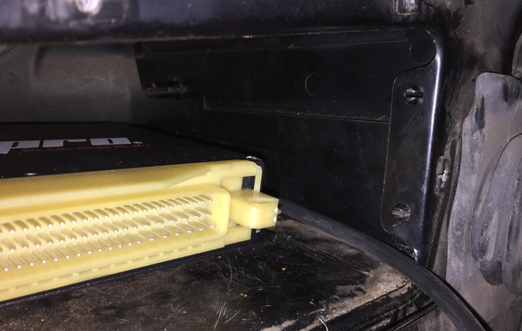
Connect the engine harness connector to the ECU by first inserting the connector's tab on the passenger's side. Swing the connector in place so that it meshes with the MSPNP's connector's pins. The engagement should be clean and smooth. If any binding occurs, reset the engagement and try again.
-
Once the pins are engaged to the connector, apply a small amount of force to the back of the connector housing and swing the metal locking tab into place to secure the connector. It should click into place if done properly.
-
At the PCV valve, pull any undesirable slack out of the previously routed vacuum hose and trim to length. Install the supplied coupling barb and connect the previously disconnected vacuum hose to the new vacuum hose. Secure the vacuum hose with zip ties.
-
Reconnect the negative battery cable.
-
At this point, power up, testing, and tuning of the MSPNP can begin. Once tuning is complete, tuck the serial cable into the ECU compartment and reinstall the ECU compartment cover and its screws as well as the cover's insulation and its clips and nuts.
Removing the Mass Air Flow Meter
Since the MSPNP calculates engine load using a MAP sensor, the air flow meter is no longer needed. While not necessary, it is recommended to remove the AFM for a small performance increase. At the very least, the air meter should be unplugged and the connector neatly tied away.
Sensor Calibration
If you need to recalibrate your temperature sensors, such as after loading firmware, here are the values to use for the stock sensors. The bias resistor value is 2490.
| Temperature (degrees F) | Temperature (degrees C) | Resistance (Ohms) |
| Coolant Temperature Sensor (CLT) | ||
| 14 | -10 | 9300 |
| 68 | 20 | 2500 |
| 176 | 80 | 335 |
| Intake Temperature Sensor (IAT) | ||
| 14 | -10 | 9300 |
| 68 | 20 | 2500 |
| 176 | 80 | 335 |
Auxiliary Function I/O Configuration
Below is a listing of functions for auxiliary I/O used from the MS3Pro module:
| I/O Point | Function |
| PWM1 | IAC Open Signal |
| PWM2 | IAC Close Signal |
| PWM3 | VANOS Control Signal |
| Injector I (INJI) | Fuel Rate Output |
| Injector J (INJJ) | AC Relay |
| Digital Frequency In 1 (DFIN1) | Vehicle Speed to Cluster |
| Digital Frequency In 2 (DFIN2) | Wheel Speed Sensor 1 (VR) |
| Digital Frequency In 3 (DFIN3) | Wheel Speed Sensor 2 (VR) |
| Digital In 1 (DI1) | Clutch Signal |
| Digital In 3 (DI3) | AC Request |
Optional Configurations
A configuration jumper is located on the lower, black circuit board inside the MSPNP. It is accessible by removing the top cover and is indicated as depicted below:
JP2: Map Sensor Selection
The MSPNP has a built in MAP sensor, but you have the option of using either the original, external OEM sensor that is under the hood or add a sensor of your own that is wired to the rear option connector. Depending on your selection, JP2 should be configured to match. Furthermore, if an external sensor is used, ensure that the scaling is properly set in TunerStudio (Tools -> Calibrate MAP/Baro).
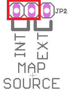
Default Selection in Red
Rear Option Connector
An auxilliary connector and harness is provided to allow you to add functionality to your car. Below is the pinout of the rear connector as viewed from the rear of the enclosure.
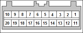
| Pin | Function | Default Function | Notes |
| 1 | High Current 1 | ||
| 2 | High Current 2 | ||
| 3 | High Current 3 | ||
| 4 | Injector G | Hi-Z Only | |
| 5 | Injector H | Hi-Z Only | |
| 6 | CMP+ | Hall Effect Only - Internal Pull-Up resistor to 5VDC | |
| 7 | Vref +5VDC | ||
| 8 | External MAP | Move Internal Jumper | |
| 9 | Analog Input 1 | MAF | |
| 10 | EGO | ||
| 11 | Digital Input 4 | ||
| 12 | Digital Input 2 | ||
| 13 | Digital Input 1 | ||
| 14 | CANL | ||
| 15 | CANH | ||
| 16 | DFIN3 | Wheel Speed 2 | VR+ Only |
| 17 | DFIN2 | Wheel Speed 1 | VR+ Only |
| 18 | Analog Input 2 | ||
| 19 | IAT | ||
| 20 | Sensor Return |
6-30-23 - 1.3

