MegaSquirt PNP Gen2 Documentation
Model/Vehicle specific installation guide for model MSPNP2-TS9395 for a 1993-1995 Toyota MR2 Turbo (3S-GTE).
Please read all documentation before installing your MegaSquirtPNP EMS and verify that you've followed all steps before starting your engine for the first time.
Physical Installation
All you'll need for a successful installation are some basic hand tools. No cutting of the original sheet metal or bracketry is required, however, two holes will need to be drilled into the rear firewall.
The MSPNP is designed to use the IAT (intake air temperature) sensor that is built into the factory air meter. However, for best performance, it is recommended to install a new IAT (included) in between the throttle body and charge pipe. This will require that the included bung be welded into the charge pipe or a third party adapter to be sourced. Details follow below.
For a thorough and professional installation, you will need the following items:
-
Phillips head screw driver
-
Flat head screw driver
-
Diagonal cutters
-
10mm socket and ratchet
-
Wire stripper
-
Electric drill
-
3/16" drill bit
-
1/4" drill bit
-
Zip Ties
-
Split wire loom
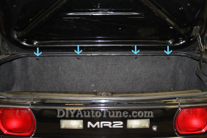
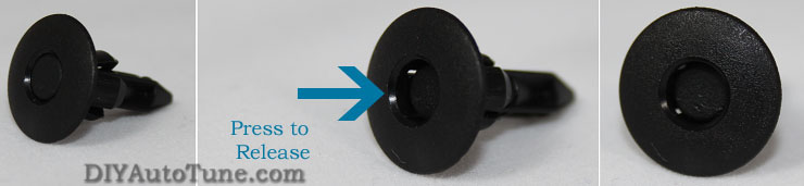
The ECU is located in the trunk between a carpeted panel and the firewall. The carpeted panel is secured in place by 4 reusable plastic trim rivets. Press the center region of the rivet until it clicks. The rivet can then easily be pulled out of the panel. After removing the rivets, gently pull the top of the panel toward you and lay it flat against the trunk floor.
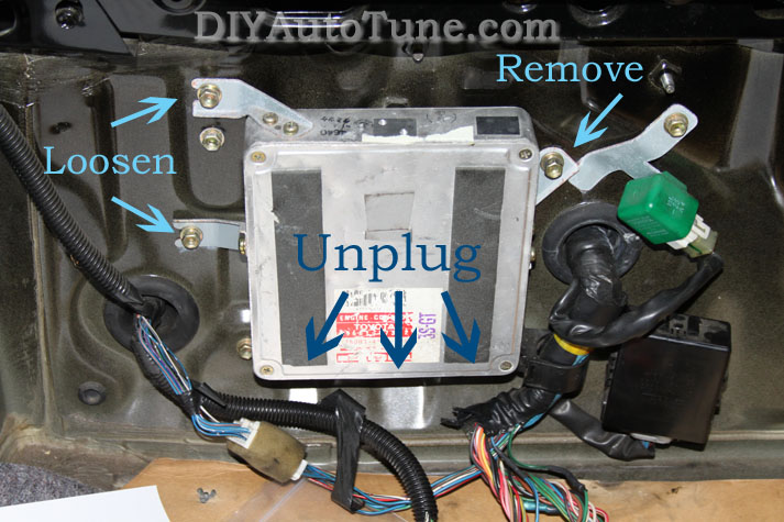
The original ECU is then located on the driver's side of the car. To remove the ECU, disconnect the three connectors at the bottom of the ECU housing, then completely remove the right most bolt and loosen the left two bolts that attach the bracket to the firewall. After the ECU is removed, replaced the bolt that was removed and tighten the other two. This will prevent any water intrusion into the trunk.
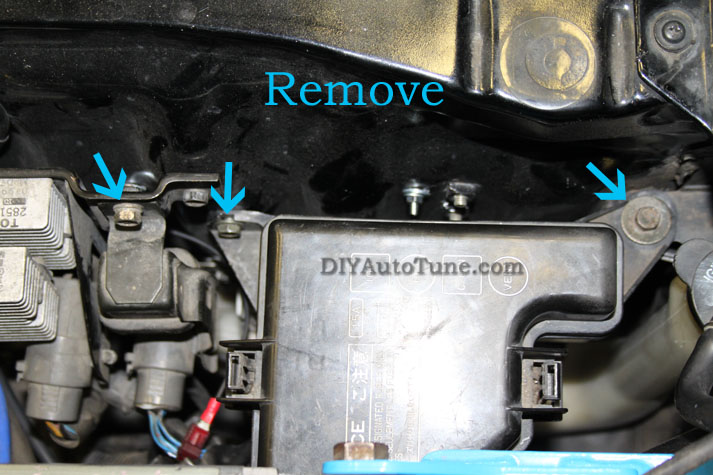
The MSPNP will be attached to the firewall using three out of the four mounting holes. One of the car's original bolts will be used while two new holes will have to be drilled into the firewall. BE AWARE OF EVERYTHING ON THE OPPOSITE SIDE OF THE FIREWALL WHEN DRILLING. There are a number of very important items there that you certainly do not want to drill into including the fuse box and fuel pump relay. To add a bit of clearance for drilling and to assist with bolting the MSPNP to the firewall, remove the two top bolts of the fuse box and the single bolt securing the fuel pump relay.
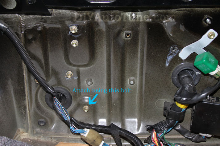
Using the existing bolt shown in the image below, secure the MSPNP to the firewall using the lower left hole on the MSPNP enclosure (connector facing down).
Once the MSPNP is secured to the firewall squarely, mark the firewall through the two upper mounting holes using a pencil or marker. Loosen the lower bolt and rotate the MSPNP out of the way to allow room for drilling holes at the locations that were just marked. Using a 3/16" drill bit, drill these two holes while using EXTREME CARE to not come into contact with items on the other side of the firewall. Once the two holes have been drilled, clean up any burrs that may be left behind.
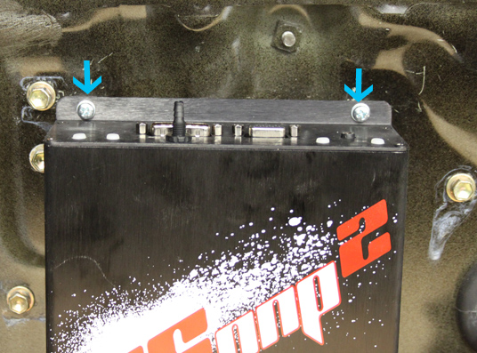
Rotate the MSPNP back into place so that the mounting holes line up with the holes you just drilled and secure into place with the included screws, washers, and nuts. At this point, you can plug in the three factory connectors to the bottom of the MSPNP. Next, you can reinstall the two fuse box bolts and one fuel pump relay bolt.
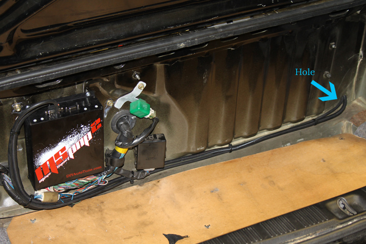
Now that the MSPNP is installed, it's time to install the vacuum line, IAT, and, if used, the boost control solenoid (not included). There is a grommet at the bottom passenger side of the trunk that is perfect for the wiring and hose to pass through (there is another hole in the driver's side of the trunk near the ECU location if you'd rather use that one). At the bare minimum, you will be running two wires from the IAT sensor and the vacuum hose through this hole. If you are installing other options, such as boost control, pass that wiring through at the same time. Route the wiring and tubing neatly between the MSPNP and this hole in the trunk, and from the opposite side of the hole to the destinations in the engine bay. Take care to keep everything away from heat sources (i.e. exhaust piping) and moving parts. Use split loom to dress up the wiring and neatly secure the wiring and tubing with zip ties.
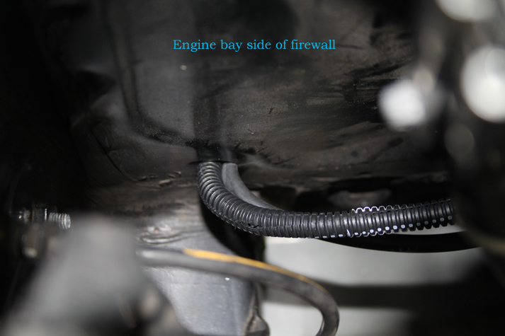
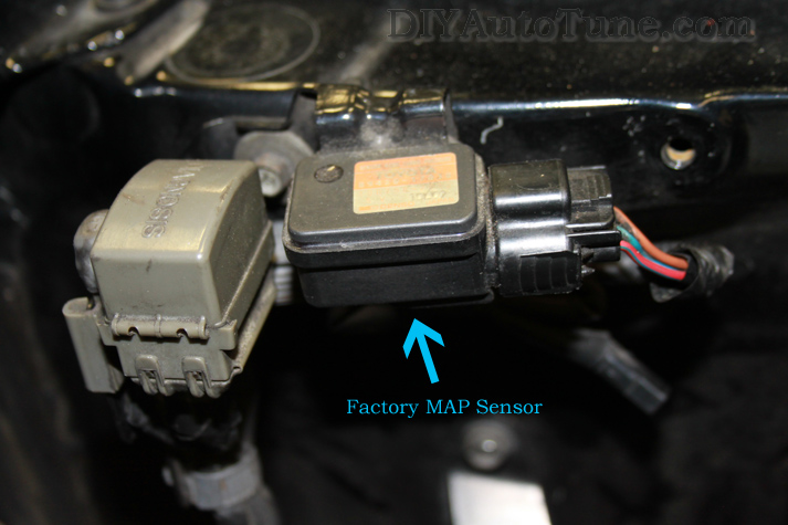
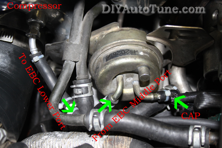
Just above the firewall hole within the engine bay is the factory MAP sensor. Remove the hose that connects to this sensor. Using the included "tee" fitting and a short piece of the included vacuum hose, connect the tee in-line with this MAP sensor and connect the MSPNP's vacuum reference source hose to the "tee".
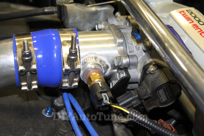
The factory IAT is located in the vane air flow meter just ahead of the turbo...not an ideal place for measuring air temperature on a turbocharged car. Therefore, a GM air temperature sensor is included with the MSPNP kit. This sensor should be installed in the charge pipe between the intercooler outlet and throttle body. The ideal place is in the piping just after the intercooler. The test car pictured below has an aftermarket adaptor (not included) with a 3/8" NPT bung just before the throttle body. Be cautious when using these types of adaptors as they tend to heat soak and the corrections within the MSPNP will cause a reduction in engine power.
The IAT sensor wiring connects to pins 10 and 15 on the V1.2's 15-pin option connector and pins 20 and 22 on the V1.3's 26-pin connector. Polarity is unimportant. Once the IAT is installed, it is necessary to disconnect the factory vane air meter. See the end of this document for instructions.
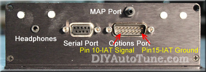
V1.2
Option Connector

V1.3
Option Connector
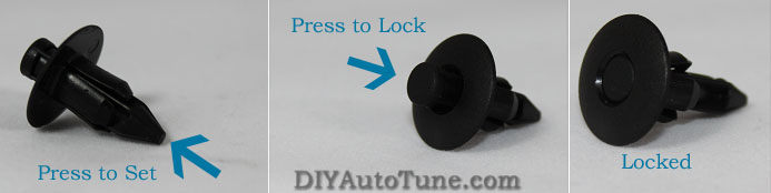
This nearly wraps up the necessary steps of the physical installation of the MSPNP! All that remains is to reinstall the carpeted trunk panel and to ensure that all wiring and hoses are neatly secured. Again, this panel is secured with 4 reusable plastic trim rivets. To "set" these rivets after removal, press on the pointed back side until the pin protrudes from the front. Insert the rivet into the trim panel hole and press the locking pin until it snaps flush and that's it!
Optional Boost Control Solenoid
The stock boost control valve does a poor job at regulating boost when commanded via a PWM signal. In fact, the stock boost control valve's really only there to act as a course trim and overall overboost protection. Therefore, it is necessary to replace it with one specifically designed for this purpose such as our electronic boost control kit (Part Number: EBC_Sol_kit). This kit is not included with the MSPNP, but it can be found on our online store at www.DIYAutoTune.com .
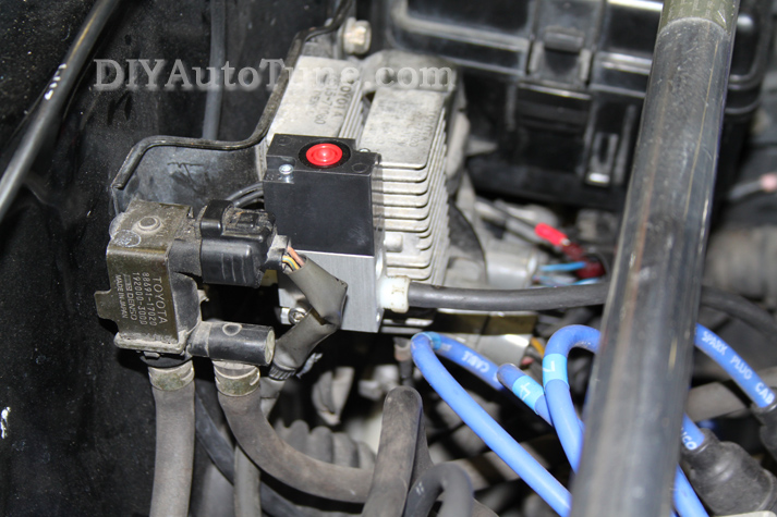
The new valve fits well between the purge control valve and injector ballast resistors.
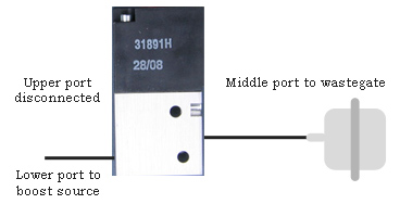
The boost control valve should be plumbed between the compressor housing and wastegate actuator as depicted below. If your wastegate actuator has two ports, cap the vent port.
At the very least, the OE boost control valve must be unplugged. It's tucked away under the intake manifold on the driver's side of the engine and may be identified by a blue or turquoise connector. If so desired, the OE valve can be removed from the car completely.
Two wires extend from the new boost control valve. These are non-polarized, so it doesn't matter which way they are wired. If using the 15-pin option port on the MSPNP2 v1.2, one wire must go to a fused, constant 12V source while the other connects to pin 1 of the DB15 on the MSPNP. Likewise, pin 7 should be used on the 26-pin port of the MSPNP2 v1.3.
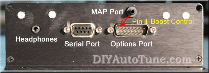
v1.2
options port
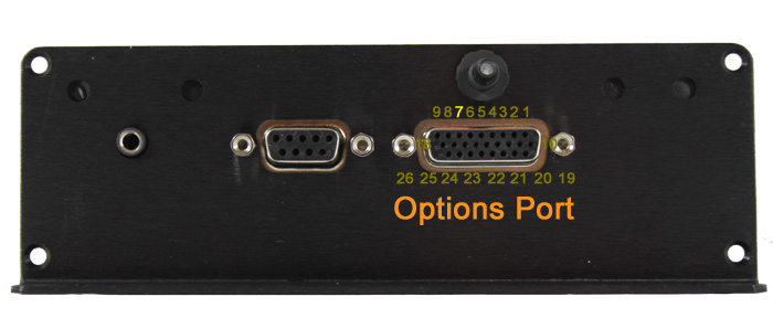
v1.3 options port
As an alternative to the options port, you can also connect both wires of the new boost control solenoid directly to the OE boost control solenoid wiring. Again, polarity is unimportant.
Verifying and Adjusting Base Timing
Because the factory ECU is no longer in control of ignition timing, it will be necessary to make checks to ensure the MSPNP is accurately delivering the proper timing. Improper ignition advance can cause engine damage if improperly set or is left unchecked.
The MSPNP will have a base ignition map loaded and ready to use. However, it is necessary to ensure that the timing advance being commanded by the MegaSquirt is in sync with what the engine is actually seeing. These steps will require the use of a timing light and a laptop with a copy of TunerStudio running.
-
Following the manufacturer's directions, carefully install a timing light on the cylinder #1 spark plug wire. Use all due caution here, as secondary ignition voltage can be as high as 100,000 volts or more. Also ensure that the timing light's cords can not get tangled in a moving engine or burned on hot components.
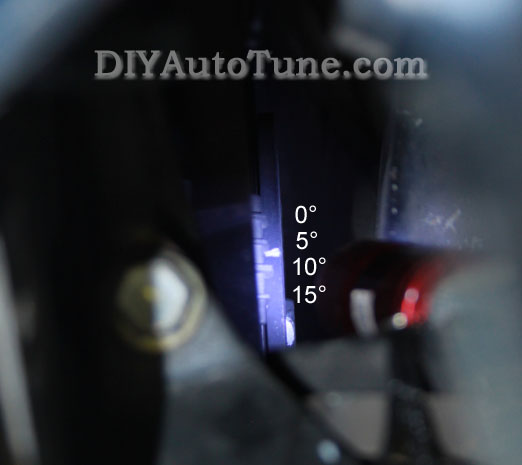
The indexing mark on the crankshaft pulley is painted white for clarity.
-
Make sure your tuning laptop is connected to your MSPNP and start your vehicle. If you have not already done so, go ahead and open up TunerStudio MS or TunerStudio Lite tuning software that you have already downloaded and installed on your laptop. Make sure that your laptop connects to the MSPNP and you are online.
-
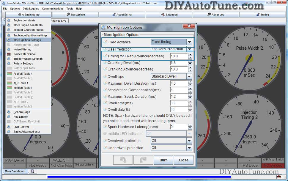
Navigate over toIgnition Settings -> Ignition Options/Decoder Wheel (For v1.2 MSPNP2s, go to Basic Setup -> More Ignition Settings). If Fixed Advance is set to Use Table, go ahead and set it to Fixed timing. This will tell the MegaSquirt to ignore our Ignition Table and hold a fixed advance. We will then need to enter a value in Timing for Fixed Advance (degrees). The value we enter here will be a static value that our MegaSquirt will use to command ignition timing. 10.0 is the default, and will work here. Burn these changes and close this menu. (Ignore the sections not highlighted in blue rectangles.)
-
Use a timing light to confirm you have 10 degrees of timing on the crank pulley. If you have more timing, increase the number called Tooth #1 Angle under Trigger Wheel Settings. If you have less, decrease the number. For example, if your Tooth #1 Angle is 60 degrees and you're seeing 15 degrees of timing, change Tooth #1 Angle to 55 degrees to bring the timing to a real 10 degrees. Note that these changes only take effect when you turn the ECU off and back on again.
-
Now we need to allow the MSPNP to command timing from the Ignition Table again. Close the Trigger Wheel Settings and go back to Ignition Settings -> Ignition Options/Decoder Wheel (For v1.2 MSPNP2s, go to Basic Setup -> More Ignition Settings). Set your Fixed Advance back to Use Table. Burn and close this menu. The MSPNP is now advancing based on your ignition table.
Adjusting VR Sensitivity
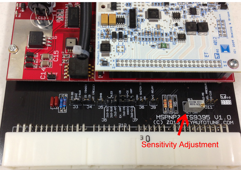
Out of the box, your MSPNP will likely have no issues starting the car as is. However, on some cars it may be necessary to increase the sensitivity of the VR trigger detection circuit. To do this, remove the top cover of the MSPNP by removing the 4 Philips head screws in the corners of the lid. With the lid off, you will see at the right side of the circuit board a gray cube with a small flat head screw on top (potentiometer). The potentiometer was set at our factory to the center of full range (50k Ohms) so it'll be easy to return to the default value if necessary. Using a small flat head screwdriver, starting in half turn, counter clockwise increments, turn the screw until you can start the car and rev it reliably. If you are unable to rev the engine reliably, turn the screw in half turn clockwise increments, beginning at the original center point.
Removing the Mass Air Flow Meter
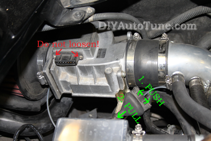
Since the MSPNP calculates engine load using a MAP sensor, the vane air flow meter is no longer needed. While not necessary, it is recommended to remove the AFM for a small performance increase. At the very least, the air meter should be unplugged and the connector neatly tied away.
The connector is held in place by a stainless steel wire around the outside of the connector. To remove the connector, use a small flat head screw driver to push the ends of the retention wire DO NOT loosen the screws on the black connector of the air meter as this will cause permanent damage.
Auxiliary Outputs
| Output | Function | State | Condition (Default) | ||
| PA0 | Boost Control | PWM | -- | ||
| WLED | TVIS | On | RPM < 4200 | ||
| ALED | Power Steering | On | RPM > 500 |

