MegaSquirt PNP Gen2 Documentation
Model/Vehicle Specific information for model MSPNP2-T8590 on a '85-'89 Toyota MR2 4AGE
Please read all documentation before installing your MegaSquirtPNP EMS, and verify you've followed all steps before starting your engine for the first time.
Physical Installation
The MR2 has the ECU located in the trunk behind the rear firewall. It is covered by a trim pannel with pop-out fasterners that you need to pry out with a pair of needle nose pliers. Once the trim panel is off, you may unscrew the ECU mounting brackets and remove the ECU. The wiring harness is attached to the ECU with squeeze plugs. Be careful removing them as they may become brittle with age. Attach the new MSPNP to the rear firewall with sheet metal screws and plug in the harness.
To connect the MSPNP's built in MAP sensor, cut the vacuum line at the fuel pressure regulator and insert the included tee fitting. Run the vacuum line from this tee through a grommet in the firewall and to the barb on the back of the MSPNP.
We also recommend routing the tuning cable from the ECU to a location on the console of the passenger compartment, somewhere where you can easily tuck it away when not in use.
At this point, it is safe to power the ECU up, but please make sure you load the appropriate startup map for your specific engine before attempting to start the vehicle. Using the wrong startup map may result in a no-start condition, or even engine damage if the engine is driven hard before the correct map is loaded.
Verifying and Adjusting Base Timing
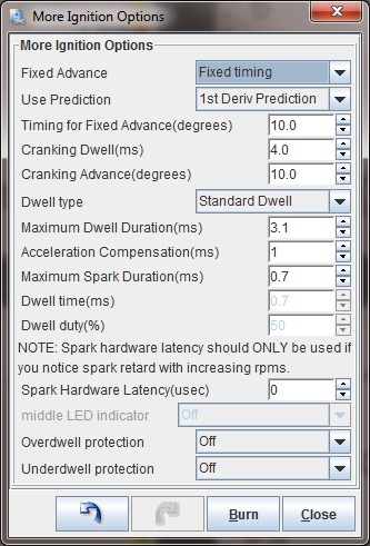
Once the MSPNP is installed, it is mandatory to check timing on your MR2. First, put the MSPNP in fixed timing mode by going to Ignition Settings -> Ignition Options/Decoder Wheel (For v1.2 MSPNP2s, go to Basic Setup -> More Ignition Settings). Set Fixed Advance to "Fixed Timing", set Timing for Fixed Advance to 10 degrees, and click the Burn button.
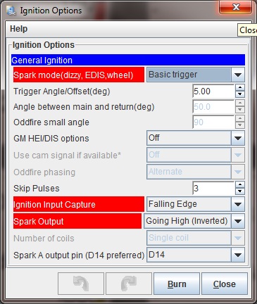
While you can adjust the timing in the same manner as a stock ECU, by adjusting the distributor angle, MSPNP gives you another option: adjust the trigger angle with TunerStudio under the spark settings. Increase the trigger angle to retard the spark, or decrease it to advance the spark. Adjust the number until the timing is at 10 degrees. MSPNP requires a trigger angle of 0 to 20 degrees on this unit to obtain full spark advance.
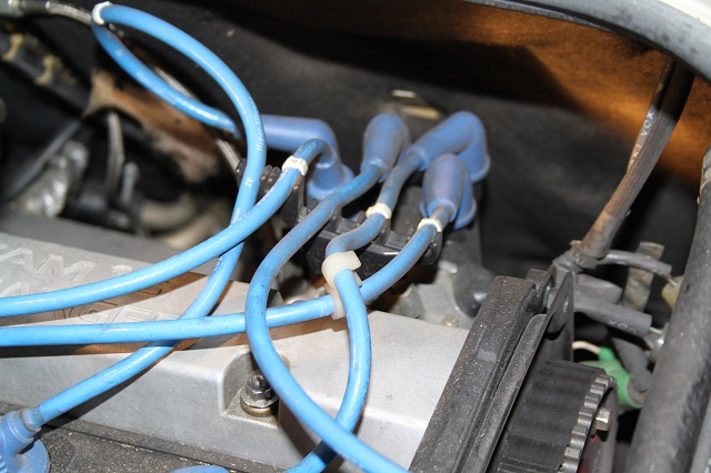
The above picture shows the location of the distributor for adjusting the timing the conventional way or if you need to adjust the sensor to obtain a better trigger angle. If you use this method for adjusting the timing advance, set the trigger angle to 10 degrees in TunerStudio and turn the distributor until the timing is at a steady 10 degrees BTDC, then lock the cam angle sensor back down there and check the timing with the light to make sure the distributor didn't slip. If you run out of adjustment, use the trigger angle setting in TunerStudio to get the correct timing.
The timing marks are on the right hand side of the engine, near the inner fender. There is a pointer rod protruding from the engine block. The timing mark on the crank pulley may be hard to see; a dab of white paint down inside the mark (wipe off the excess) can help here. Once you have adjusted the trigger angle and/or cam angle sensor to get 10 degrees BTDC, turn off the fixed timing mode by changing the Fixed Timing setting to "Use Table."
TVIS Control
Your MSPNP can turn TVIS on and off using Output 1 (formerly ALED). The conditions that activate TVIS can be set under Extended -> Output Port Settings.
Removing the Vane Air Flow Meter
This is completely optional of course... but if you'd like to rid yourself of that pesky and restrictive Air Flow Meter you need to concern yourself with two things. One, the stock IAT sensor is inside that housing. Two, the stock AFM controls the Fuel Pump, as in the fuel pump will only run with the AFM flapper door is open (when the engine is starting or running and air is flowing through the flapper). This allows the AFM to stop the fuel pump from running in the event then engine stops running, such as if you have an accident. When you remove the AFM, you need to put the MSPNP in charge of the fuel pump.
IAT Sensor:
Simply wire a GM Open Element IAT Sensor into your factory wiring harness at the AFM connector. You can poke wires into the AFM connector, or you can cut and splice. Wire one lead of the GM Sensor to the Brown Wire at the AFM Connector, and the other lead of the GM Sensor to the Yellow wire at the AFM Connector. Finally, you'll need to recalibrate it now back to the GM IAT Sensor settings. Go back to 'Tools > Calibrate Thermistor Tables'. Choose Intake Air Temp Sensor. Choose 'GM' under 'Common Sensor Defaults'. Click Write to Controller and then click Close.
Fuel Pump Control:
To control the fuel pump, you need to do two things. You need to run a jumper wire between two wires at the AFM first. The GRN/RED wire and the BLUE/RED Wire. Connect these together.
Next, you need to set the MSPNP so that it sends the fuel pump output to the AFM. You will need to unscrew the lid from the MSPNP. There is a switch on the lowest circuit board marked S1. Place this switch in the down position. If for some reason you need to re-install the AFM, this switch needs to be in the up position.
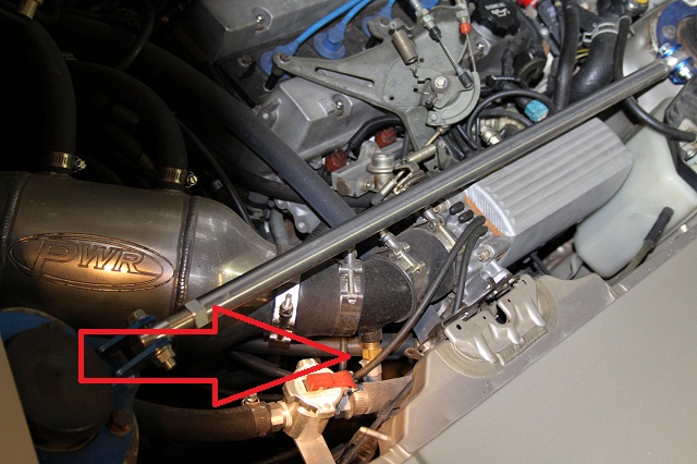
Note: If you are using the MSPNP with a turbo or supercharger:
You will definitely want to delete the AFM and put an IAT sensor in the location pictured above which is just before the throttle body inlet. The IAT needs to measure the air temperature as it's entering the engine, not the ambient air temperature in the engine bay as would be measured by the AFM. Only by placing the IAT just before the throttle body can an accurate air temperature measurement be taken AFTER the compressor has heated the air, and the intercooler has cooled it. Accurate air temps are needed for proper fueling and ignition advance calculations. The picture below shows where the sensor is on our MR2 project car.
Sensor Calibration
If you need to recalibrate your temperature sensors, such as after loading firmware, here are the values to use for the stock sensors. These work for both factory CLT and IAT sensors. GM IAT sensors can use the defaults in TunerStudio
| Temperature (degrees F) | Temperature (degrees C) | Resistance (Ohms) | ||
| -4 | -20 | 15000 | ||
| 68 | 20 | 2500 | ||
| 140 | 60 | 550 |
5-7-20 - 1.1

