MegaSquirt PNP Gen2 Documentation
Model/Vehicle specific installation guide for model MSPNP2-NS9501 for a 1995-1998 Nissan 240 with the 2.4L KA24 engine.
Please read all documentation before installing your MegaSquirtPNP EMS and verify that you've followed all steps before starting your engine for the first time.
Physical Installation
All you'll need for a successful installation are some basic hand tools. No cutting or drilling of the original sheet metal or bracketry is required.
For a thorough and professional installation, you will need the following items:<
-
10mm socket and ratchet
-
Phillips head screw driver
-
Small flat head screw driver
-
Zip ties
-
Timing light
-
Laptop with TunerStudio installed
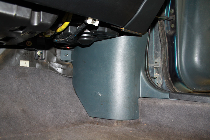
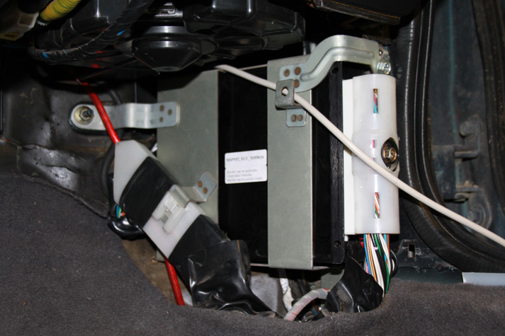
The stock ECU is located in the passenger's side footwell, just behind the kick panel in front of the door. To remove the kick panel, first remove the lower door sill cover by grasping the end and firmly pull upward. Afterward, the kick panel simply pulls away.
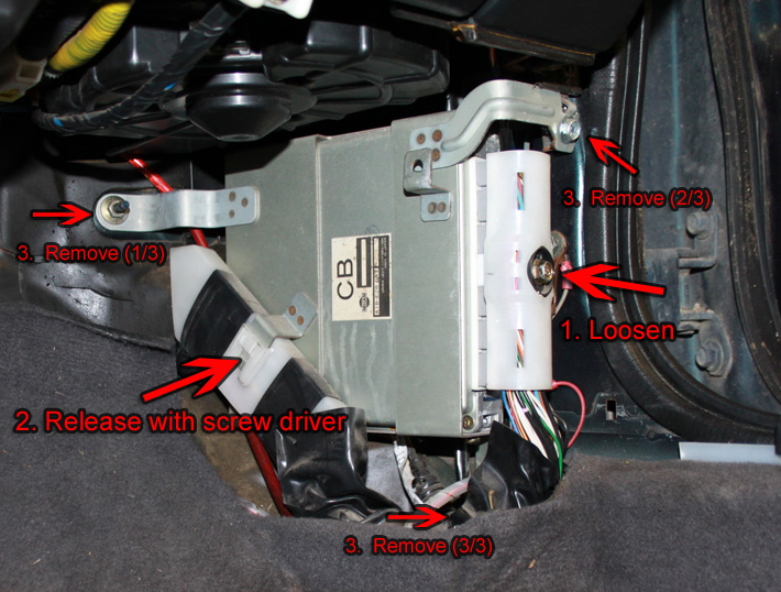
The ECU is tucked away behind a bracket that is secured by three screws. To remove the stock ECU, first loosen the bolt that secures the main harness connector. The bolt is captive and should not be removed once it is loose. Pull the white connector away from the ECU. Next, release the harness keeper by lifting the center locking tab with a small flat head screw driver. Slide the harness and keeper towards the floor. Lastly, remove the three bolts using a 10mm socket and free the ECU.
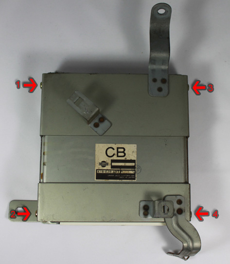
The original ECU bracket will be reused to secure the MSPNP. Remove the four Philips head screws to release the bracket. Discard the stock ECU and the four screws.
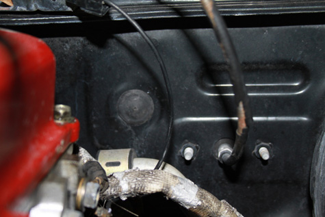
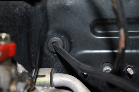
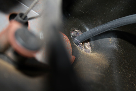
Next, you must run a vacuum line from the engine, through the firewall, and to where the MSPNP will reside. There is a small plug just above, and to the left of the throttle cable in the firewall. This is where the vacuum line will pass into the passenger compartment. Make a hole roughly the size of the vacuum line in this cap and pass the vacuum hose through.
 |
 |
||
 |
|||
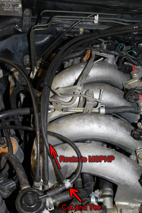
The easiest place to source a vacuum reference is from the fuel pressure regulator vacuum hose. Cut this hose and insert the provided tee as shown below. After the tee is installed, connect one end of the vacuum line for the MSPNP here, route it neatly through the engine bay, and secure it with zip ties to prevent movement and entanglement. NOTE: Avoid pulling the zip ties so tight as to collapse the vacuum hose. The zip ties should only be snug at best.
Inside the car, route the vacuum hose behind the heater box (under the dash) and across to the location of the ECU. Pay careful attention to avoid contact and entanglement with moving parts such as the pedals and climate control cables. Secure the hose with zip ties. NOTE: Avoid pulling the zip ties so tight as to collapse the vacuum hose. The zip ties should only be snug at best.
Before installing the MSPNP, be sure connect the tune cable as wells as the vacuum hose to the back. Next, place the MSPNP in place with the logo facing the car chassis and the connector facing toward the back of the car. Fit the original ECU bracket over the MSPNP, align the three mounting holes to the chassis, and screw into place - the fit with tune cable will be very tight, so patience and due diligence is required here. Reconnect the main harness connector and snugly tighten the center bolt (don't over tighten!).
All that remains is to reinstall the trim work. Depending on your installation, it may be required to trim a small amount of flashing from the inside of the kick panel. Simply remove this extra plastic with a sharp knife or diagonal cutters. After the kick panel is fitted, reinstall the door sill cover.
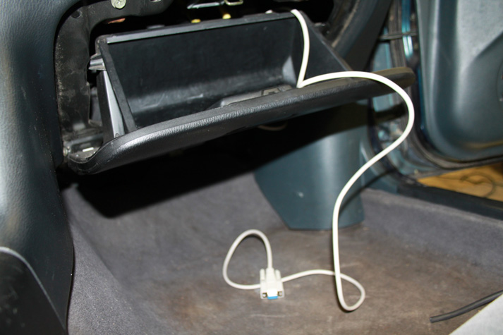
Afterwards, route your tuning cable to an area such as the glove box and the physical installation will be complete.
Verifying and Adjusting Base Timing
Because the factory ECU is no longer in control of ignition timing, it will be necessary to make checks to ensure the MSPNP is accurately delivering the proper timing. Improper ignition advance can cause engine damage if improperly set or is left unchecked.
The MSPNP will have a base ignition map loaded and ready to use. However, it is necessary to ensure that the timing advance being commanded by the MegaSquirt is in sync with what the engine is actually receiving. These steps will require the use of a timing light and a laptop with a copy of TunerStudio running.
-
Connect a timing light on the cylinder #1 spark plug wire. Use all due caution here, as secondary ignition voltage can be as high as 100,000 volts or more. Also ensure that the timing light's cords can not get tangled in moving engine parts or burned on hot components.
-
Make sure your tuning laptop is connected to your MSPNP and start your vehicle. If you have not already done so, start TunerStudio MS or TunerStudio Lite. Make sure that your laptop connects to the MSPNP and you are online.
-
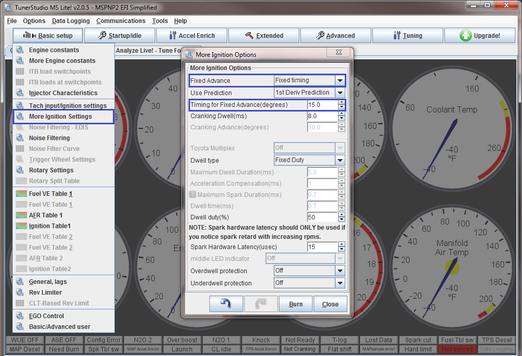
Navigate to Ignition Settings -> Ignition Options/Decoder Wheel (For v1.2 MSPNP2s, go to Basic Setup -> More Ignition Settings). If "Fixed Advance" is set to "Use Table", set it to "Fixed timing". This will tell the MSPNP to ignore the ignition table and hold a fixed advance angle. Set this value to 15.0 degrees. Burn these changes and close this menu. (Ignore the sections not highlighted in blue rectangles.)
-
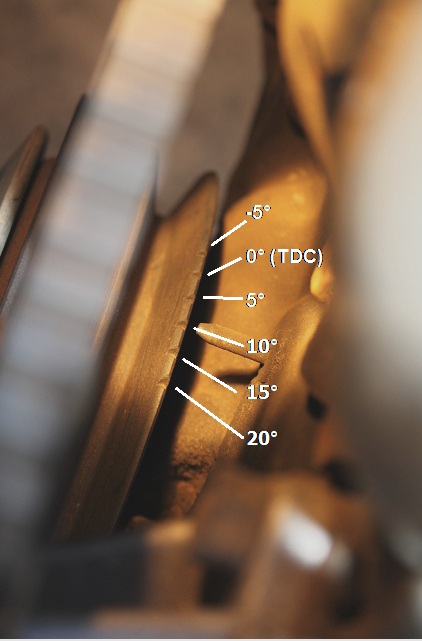
Use a timing light to confirm that you have 15 degrees of timing at the crank pulley -- If you have more timing, decrease the "Trigger Angle" value under the Ignition Settings -> Ignition Options/Decoder Wheel (For v1.2 MSPNP2s, go to Basic Setup -> More Ignition Settings) dialog box. If you have less, increase this value.
-
Close the "Ignition Options" dialog and go back to the "More Ignition Settings" menu under the "Basic Setup" tab. Set "Fixed Advance" back to "Use Table". Burn and close this menu. Cycle power to the MSPNP (turn the car off and back on). The MSPNP is now commanding timing advance based on the ignition table.
Removing the Mass Air Flow Meter
Since the MSPNP calculates engine load using a MAP sensor, the air flow meter is no longer needed. While not necessary, it is recommended to remove the AFM for a small performance increase. At the very least, the air meter should be unplugged and the connector neatly tied away.
Optional Configurations
Several jumpers are located on the lower, black circuit board inside the MSPNP. These are accessible by removing the top cover and are indicated as depicted below. However, these dictate the platform with which the MSPNP is design for. These should not be changed and are only included here for reference.
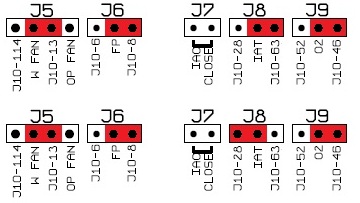 |
NS9501A |
| NS9501B |
Default settings indicated in red.
Alternate Distributor Trigger Disc and Sequential Injection
On some cars, users may experience difficult starting with kickbacks and back fires. We have created a bolt in trigger disc as an optional mod you can install with the MSPNP (not included). This trigger disc has a pattern that works better with MS2, allowing more precise timing control, sequential injection, and distributorless ignition conversions. It bolts right into the stock distributor with no cutting or rewiring required (unless you change to distributorless ignition). This trigger disc is available in two sizes to accommodate different models. KA24DE motors always need the 50 mm disc (Part No. TW_SR20).
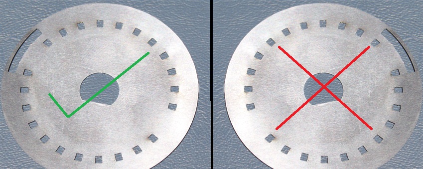
To install, simply remove the distributor cap and rotor. There's a single Philips head screw that holds the trigger disc and its mounting plate in place. Unscrew this, remove the disc and put ours in its place and bolt it back together. Our trigger discs are meant to be installed with the side shown below facing up as you look into the distributor; if they are installed upside down, you'll need to change the trigger angles in TunerStudio at the minimum.
Once you have the disc installed, use these settings in TunerStudio::
- Settings under Ignition
Settings:
- Spark mode: Toothed Wheel
- Ignition input capture: Falling Edge
- Spark output will depend on what output setup you're using. IGN-1As, LS coils, and QuadSparks all use Going High / Inverted. Getting this setting wrong can damage the ignition module and/or coils. If the ignition module or coils get hot with the key on and the engine off, turn the key off immediately and select the opposite output setting.
- Settings under Ignition
Settings:
- Trigger wheel arrangement: Dual wheel with missing tooth
- Trigger wheel teeth: 12
- Missing Teeth: 1
- Tooth #1 angle: 345 (This varies slightly between individual engines. Check with a timing light and adjust as needed.))
- Wheel speed: Crank wheel
- Second trigger active on: Rising edge
Because the distributor has some built in adjustment, it's likely that many installs may need as much as 20 degrees of adjustment to the Tooth #1 angle setting, so you will need to check your timing with a timing light. Treat these values as a starting point, not the definitive, final numbers.
If you are converting to distributorless ignition, you will also set thee Number of Coils setting too Wasted Spark. This will let you use the spark outputs on the option connector. Spark A fires cylinders 1 and 4, and spark B fires cylinders 2 and 3. These signals may be wired directly to GM LS coils or DIYAutoTune.com's IGN-1A coils (each output will fire two coils), or other coils that take a 5 volt logic level trigger and have a built in ignition module. Other coils will need an ignition module, such as DIYAutoTune.com's QuadSpark.
To enable sequential injection, go to the Advance menu, select Sequential Injection, and set Sequential Injection to "Sequential / Semi-Sequential." Click Burn, and turn the MSPNP off. There are a couple jumpers that need to be adjusted inside the MSPNP before you turn it back on. This will put the MSPNP hardware in sequential injection mode. Remove the top cover of the MSPNP and move the jumpers as indicated below into the positions highlighted in red. Note that other jumpers may be populated that are not indicated on these diagrams. Focus is emphisized solely on the jumpers that are to be moved.
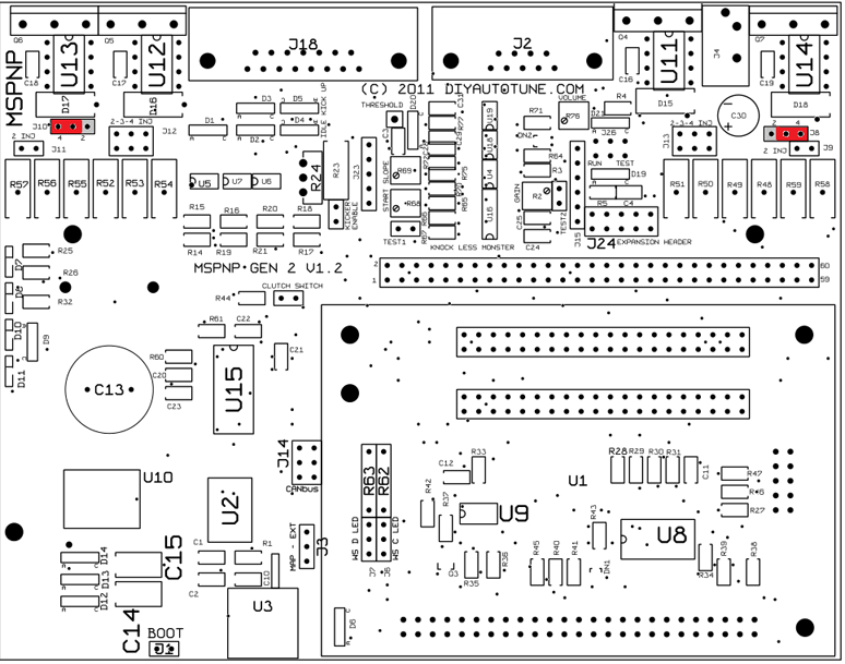
For ECUs utilizing the version 1.2 upper PCB, move jumpers J8 and J10 into the locations highlited in red:
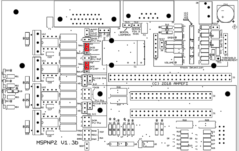
For ECUs utilizing the version 1.3 upper PCB, move jumpers INJC and INJD into the locations highlited in red:
Sensor Calibration
If you need to recalibrate your temperature sensors, such as after loading firmware, here are the values to use for the stock sensors. The bias resistor is 2490 ohms. Use this chart for the CLT sensor.
| Temperature (degrees F) | Temperature (degrees C) | Resistance (Ohms) | ||
| 68 | 20 | 2500 | ||
| 194 | 90 | 250 | ||
| 230 | 110 | 145 |
Use this chart for the factory IAT sensor. GM IAT sensors can use the defaults in TunerStudio.
| Temperature (degrees F) | Temperature (degrees C) | Resistance (Ohms) | ||
| 14 | -10 | 9000 | ||
| 68 | 20 | 2500 | ||
| 122 | 50 | 820 |
5-7-20 - 1.2

