MegaSquirt PNP Gen2 Documentation
Model/Vehicle Specific information for model MSPNP2-NS8994 on a '90-'95 Hardbody pickup with the KA24E
Please read all documentation before installing your MegaSquirtPNP EMS, and verify you've followed all steps before starting your engine for the first time.
Physical Installation
These trucks have the ECU under the seat, to the right of the truck. If you have a bench seat, you'll need to remove the whole seat to install your MSPNP. If you have bucket seats, you only need to remove the passenger seat. Once the seat is out, you can unbolt the ECU. Remove the center bolt in the ECU connector to unplug the connector. Fasten the MSPNP to the floorboard with the included sheet metal screws and plug in the factory ECU harness connector. Note that this connector must be bolted down tightly for the connector to work - often a bit tighter than you can get with a nut driver, so you will need a wrench handle for this. Finger tight is asking for trouble. (Trust us, we've made that mistake a couple times in testing when someone was in a hurry.)
You'll need to hook up the MSPNP's built in MAP sensor. Cut the vacuum line at the fuel pressure regulator and insert the included tee fitting. Run the vacuum line from this tee through a grommet in the firewall and to the barb on the back of the MSPNP.
We also recommend routing the tuning cable from the ECU to a location on the console of the passenger compartment, somewhere where you can easily tuck it away when not in use.
At this point, it is safe to power the ECU up, but please make sure you load the appropriate startup map for your specific engine before attempting to start the vehicle. Using the wrong startup map may result in a no-start condition, or even engine damage if the engine is driven hard before the correct map is loaded.
Verifying and Adjusting Base Timing
Once the MSPNP is installed, it is mandatory to check timing on all NS8994 applications. First, put the MSPNP in fixed timing mode by going to the Ignition Settings -> Ignition Options/Decoder Wheel (For v1.2 MSPNP2s, go to Basic Setup -> More Ignition Settings)s. Set Fixed Advance to "Fixed Timing", set Timing for Fixed Advance to 10 degrees, and click the Burn button.
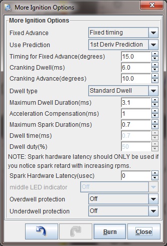
While you can adjust the timing in the same manner as with a stock ECU by adjusting the distributor, MSPNP gives you another option: adjust the trigger angle with TunerStudio under the spark settings. Increase the trigger angle to retard the spark, or decrease it to advance the spark. Adjust the number until the timing is at 10 degrees. MSPNP requires a trigger angle of at least 50 degrees on this unit to obtain full spark advance.
If you adjust the distributor for adjusting the timing advance, set the trigger angle to default value of 72 degrees in TunerStudio and turn the distributor until the timing is at a steady 10 degrees BTDC, then lock the cam angle sensor back down there and check the timing with the light to make sure the distributor didn't slip. If you run out of adjustment, use the trigger angle setting in TunerStudio to get the correct timing.

The timing marks are on the front of the engine. The timing mark on the crank pulley may be hard to see, but there is a dab of white paint at 10 degrees. Once you have adjusted the trigger angle and/or cam angle sensor to get 10 degrees BTDC, turn off the fixed timing mode by changing the Fixed Timing setting to "Use Table."
Intake Air Temperature Sensors, and Removing the Mass Air Flow Sensor
For some reason, Nissan put an intake air temperature sensor on the KA24E, but omitted it on the KA24DE. We strongly recommend all KA24DE users to add a GM intake air temperature (IAT) sensor. This is optional on the KA24E, but may help resolve issues if the sensor gives false hot readings where it is absorbing heat from the intake manifold. The best location for an IAT sensor is just upstream of the throttle body. There are two points on the MSPNP where you can connect an IAT sensor. If racing class rules do not permit you to remove or even unplug the mass air flow sensor, you may wire the IAT to pins 10 and 15 on the 15-pin option connector on the v1.2 board and pins 20 and 22 on 26-pin option connector on the v1.3 board.
For most users, you'll want to unplug the MAF and connect the IAT sensor to the pins corresponding to the white and orange wires ("B" and "C" pins) on the mass air flow sensor. You can use the pins in our IAT sensor kit, plugged into the MAF connector, and fold over and secure with high temperature tape. 3M makes tape, such as Super88, that can handle the temps found in engine bays.
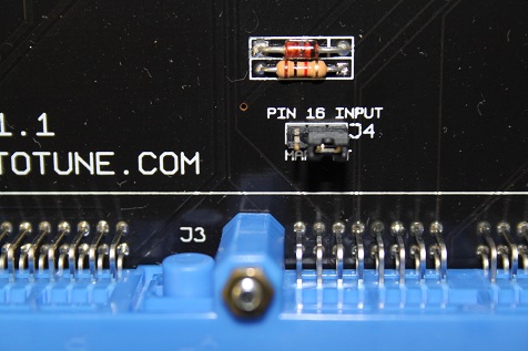
If you are wiring the IAT sensor in through the MAF connector, it is necessary to modify a jumper inside the MSPNP. Remove the lid and find 3 pin header on the lowest board labeled "Pin 16 input". Pull the connecting jumper off this header and place it on the center pin and the rightmost pin, marked "AT".
After installing the IAT, turn the ignition key on but do not start the engine. Connect to the MSPNP with TunerStudio. Go to the Tools menu and select Calibrate Thermistor Tables, select Air Temperature Sensor, and select GM from the Common Sensor Values drop down box. Leave the bias resistor setting at 2490.0 ohms. Click Write to Controller. This will update the sensor calibration in the MSPNP.
Once you have an IAT sensor in place, you can remove the MAF and replace it with a length of straight pipe for a less restrictive intake.
Note: If you are using the MSPNP with a turbo or supercharger:
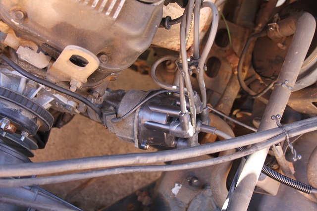
After you remove the AFM, install the IAT sensor in the location pictured above which is just before the throttle body inlet. The IAT needs to measure the air temperature as it's entering the engine, not the ambient air temperature in the engine bay. Only by placing the IAT just before the throttle body can an accurate air temperature measurement be taken AFTER the compressor has heated the air and the intercooler has cooled it. Accurate air temperature measurements are needed for proper fueling and ignition advance calculations.
Swirl Valve Control
Your MSPNP is set up to use the PM4 - Accel LED output for controlling the swirl valve, under Extended -> Output Port Settings. This valve is used on factory installations to boost low RPM torque, but should be turned off at high RPM.
Alternate Distributor Trigger Disc and Sequential Injection
We've created a bolt in trigger disc as an optional mod you can install with the MSPNP (not included). This trigger disc has a pattern that works better with MS2, allowing more precise timing control, sequential injection, and distributorless ignition conversions. It bolts right into the stock distributor with no cutting or rewiring required (unless you change to distributorless ignition). This trigger disc is available in two sizes to accommodate different models. KA24DE motors always need the 50 mm disc. Nissan used several distributor sources for the KA24E, and you may need a 50 mm (Part No. TW_SR20) or 54 mm disc (Part No. TW_L28ET). Please check before ordering.
To install, simply remove the distributor cap and rotor. There's a single Philips head screw that holds the trigger disc and its mounting plate in place. Unscrew this, remove the disc and put ours in its place and bolt it back together. Our trigger discs are meant to be installed with the side shown below facing up as you look into the distributor; if they are installed upside down, you'll need to change the trigger angles in TunerStudio at the minimum.
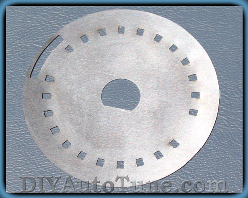
(50 mm trigger wheel)
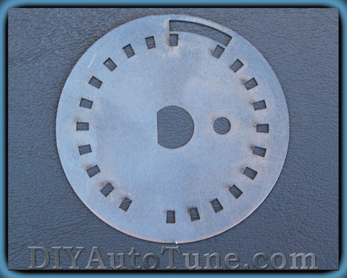
(54 mm trigger wheel - note the small hole)
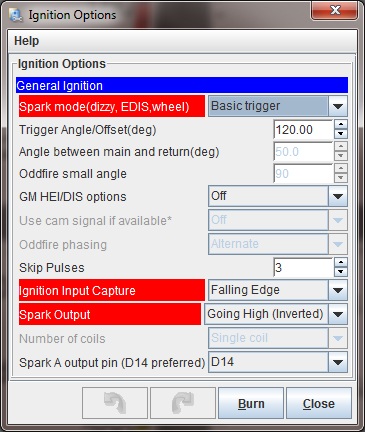
Once you have the disc installed, use these settings in TunerStudio:
- Settings under Ignition
Settings:
- Spark mode: Toothed Wheel
- Ignition input capture: Falling Edge
- Spark output will depend on what output setup you're using. IGN-1As, LS coils, and QuadSparks all use Going High / Inverted. Getting this setting wrong can damage the ignition module and/or coils. If the ignition module or coils get hot with the key on and the engine off, turn the key off immediately and select the opposite output setting.
- Settings under Ignition
Settings:
- Trigger wheel arrangement: Dual wheel with missing tooth
- Trigger wheel teeth: 12
- Missing Teeth: 1
- Tooth #1 angle: 345 (This varies slightly between individual engines. Check with a timing light and adjust as needed.)
- Wheel speed: Crank wheel
- Second trigger active on: Rising edge
Because the distributor has some built in adjustment, it's likely that many installs may need as much as 20 degrees of adjustment to the Tooth #1 angle setting, so you will need to check your timing with a timing light. Treat these values as a starting point, not the definitive, final numbers.
If you are converting to distributorless ignition, you will also set the Number of Coils setting to Wasted Spark. This will let you use the spark outputs on the option connector. Spark A fires cylinders 1 and 4, and spark B fires cylinders 2 and 3. These signals may be wired directly to GM LS coils or DIYAutoTune.com's IGN-1A coils (each output will fire two coils), or other coils that take a 5 volt logic level trigger and have a built in ignition module. Other coils will need an ignition module, such as DIYAutoTune.com's QuadSpark.
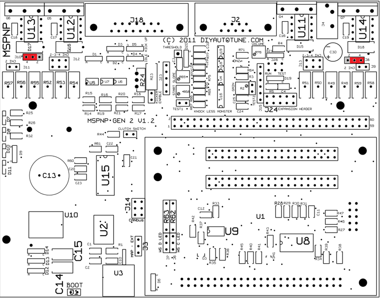
To enable sequential injection, go to the Advance menu, select Sequential Injection, and set Sequential Injection to "Sequential / Semi-Sequential." Click Burn, and turn the MSPNP off. There are a couple jumpers that need to be adjusted inside the MSPNP before you turn it back on. This will put the MSPNP hardware in sequential injection mode. Remove the top cover of the MSPNP and move the jumpers as indicated below into the positions highlighted in red. Note that other jumpers may be populated that are not indicated on these diagrams. Focus is emphisized solely on the jumpers that are to be moved.
For ECUs utilizing the version 1.2 upper PCB, move jumpers J8 and J10 into the locations highlited in red:
For ECUs utilizing the version 1.3 upper PCB, move jumpers INJC and INJD into the locations highlited in red:

Sensor Calibration
If you need to recalibrate your temperature sensors, such as after loading firmware, here are the values to use for the stock sensors. The bias resistor is 2490 ohms. Use this chart for the CLT sensor.
| Temperature (degrees F) | Temperature (degrees C) | Resistance (Ohms) | ||
| 68 | 20 | 2500 | ||
| 194 | 90 | 250 | ||
| 230 | 110 | 145 |
Use this chart for the factory IAT sensor. GM IAT sensors can use the defaults in TunerStudio.
| Temperature (degrees F) | Temperature (degrees C) | Resistance (Ohms) | ||
| 14 | -10 | 9000 | ||
| 68 | 20 | 2500 | ||
| 122 | 50 | 820 |
5-7-20 - 1.2

