MegaSquirt PNP Gen2 Documentation
Model/Vehicle Specific information for model MSPNP2-MM9697 on a 1996-1997 Mazda Miata 1.8
Please read all documentation before installing your MegaSquirtPNP EMS, and verify you've followed all steps before starting your engine for the first time.
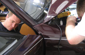
Physical Installation
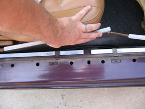
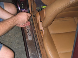
- Remove the right hand door trim panel. Fold and slide the passenger seat forward and lift the carpet behind it to expose the stock ECU.
- Remove the three 10mm nuts holding the stock ECU in place.
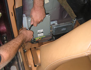
- Fold the ECU over forward (there's just enough room) and remove
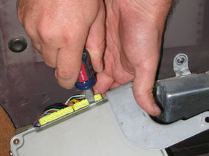
the wiring harness from the ECU. The easiest way to do this is to
reach around the bottom and push down on the release tab with your
finger, while GENTLY prying the connector from the opposite side out
of the ECU with a flathead screwdriver. Do this carefully and you'll
do no damage to your stock harness or ECU.
- Now it is time to route the MAP line. Mazda happens to have
provided a plug behind the windshield washer reservoir that's about
the perfect size for the MAP hose.
- Pop the plug out and drill a hole in it. Now the plug is a
grommet. The hole should be just large enough to run the hose
through.
- Pull about 2-3' of the hose through the grommet.
- This next step is much easier if you have two people,
one feeding the hose in from the engine compartment side and the
other one pulling from the passenger compartment. Feed the hose in
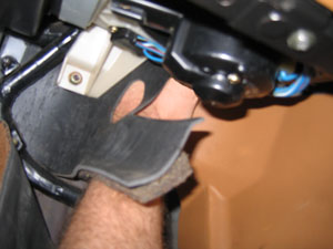
through the hole in the engine compartment. Have someone else reach
up behind the firewall insulation and feel for the hole; it's about
as far to the right as it's possible to reach. You will probably
find the hose before you find the hole. Pull the hose in through the
firewall far enough to reach the MSPNP MAP sensor hole.
- From the engine side, stick a screwdriver thru the hole pointing down, use it to push the insulation back a bit.
- From inside have someone feel behind the insulation for the screwdriver, this will help them to locate the hole.
- From the engine side, remove the screwdriver and push the hose thru the hole and down. Feed it thru while someone pulls it thru from the inside.
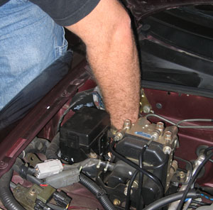
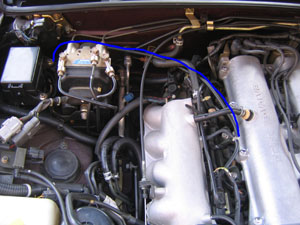
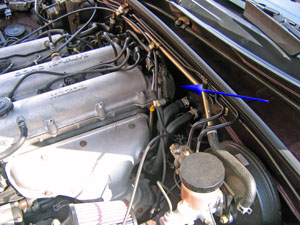
- Inside the engine compartment, route the MAP hose along the
firewall, turning to follow between the intake manifold and valve
cover (over the fuel rail) and use the vacuum tee to connect to the
intake manifold as shown above. You may need to 'fresh cut' the
factory hose by 1cm to get a tight seal as it will have expanded
some. Don't cut the included MAP hose just yet, you'll cut it to
length at the other end.
- Pull any excess hose through the firewall into the passenger
compartment and verify your routing in the engine bay.
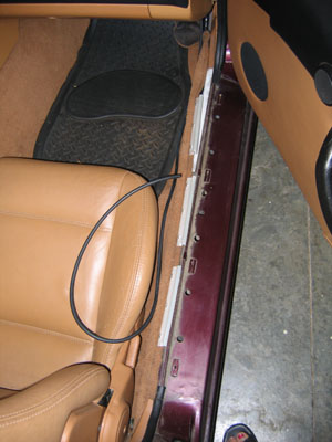
- Back inside the car, lay the MAP hose carefully under the edge of the carpet following the wiring harness to the ECU.
- Plug in the tuning cable first. Then the factory ECU connectors. Lastly plug in the MAP hose.
- Drill holes in the rear firewall and screw the MSPNP to the firewall with the provided sheet metal screws. In our experience two screws up top are usually enough, though four are provided.
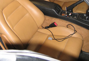
- Route the tuning cable between the seat and tunnel and it is
ready to plug in... (or be tucked away when not needed)
- Fold down the firewall carpet, reinstall the door trim, and tuck the insulation back in place on the front firewall. The ECU is now installed, but you will want to check your timing, as described below.
At this point, it is safe to power the ECU up, but please make sure you load the appropriate startup map for your specific engine before attempting to start the vehicle. Using the wrong startup map may result in a no-start condition, or even engine damage if the engine is driven hard before the correct map is loaded.
Verifying and Adjusting Base Timing
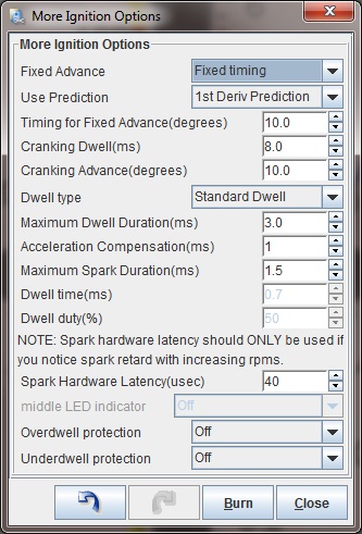
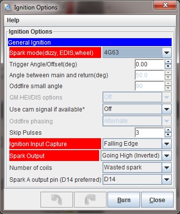
Once the MSPNP is installed, it is mandatory to check timing on Miatas. First, put the MSPNP in fixed timing mode by going to Ignition Settings -> Ignition Options/Decoder Wheel (For v1.2 MSPNP2s, go to Basic Setup -> More Ignition Settings). Set Fixed Advance to "Fixed Timing", set Timing for Fixed Advance to 10 degrees, and click the Burn button.
While you can adjust the timing in the same manner as you would with a stock ECU, by adjusting the cam angle sensor, MSPNP gives you another option: adjust the trigger angle within TunerStudio under the spark settings. Increase the trigger angle to retard the spark, or decrease it to advance the spark. Adjust the number until the timing is at 10 degrees. TunerStudio lets you adjust the trigger angle from 0 to 20 degrees. If the trigger angle is out of this range, you should rotate the cam angle sensor to give you more trigger angle.
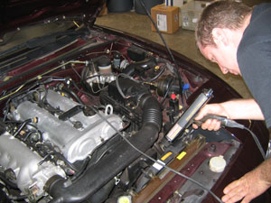
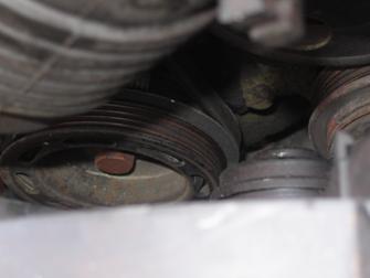
The above picture shows the location of the cam angle sensor for adjusting the timing the conventional way or if you need to adjust the sensor to obtain a better trigger angle. Use a 12 mm wrench to loosen the bolt holding the sensor in place so you can adjust the sensor position. If you use this method for adjusting the timing advance, set the trigger angle to 10 degrees in TunerStudio and turn the cam angle sensor until the timing is at a steady 10 degrees BTDC, then lock the cam angle sensor back down there and check the timing with the light to make sure the CAS didn't slip. If you run out of adjustment, use the trigger angle setting in TunerStudio to get the correct timing.
The timing marks are on the front of the engine. The timing mark on the crank pulley may be hard to see; a dab of white paint down inside the mark (wipe off the excess) can help here. Once you have adjusted the trigger angle and/or cam angle sensor to get 10 degrees BTDC, turn off the fixed timing mode by changing the Fixed Timing setting to "Use Table."
Fan control
Your MSPNP is set up to use the PM4 - Accel LED output for fan control. The fan will come on whenever this output is on.
Removing the Mass Air Flow Meter
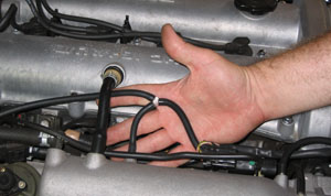
Since the MSPNP is speed density, you don't need to have the restictive factory mass air flow sensor in place. We've found gains of 3 to 5 horsepower by replacing the sensor with a length of straight pipe. You'd think this sensor would be less restrictive than the vane air flow meter on the 1.6, but our tests have shown it's equally bad for horsepower. This does require one wiring change, as there's an air temperature sensor in there. You'll need to substitute a GM IAT sensor with the air flow meter gone. This sensor connects to the third and fourth pins on the IAT connector, as shown in the graphic below. IAT sensors have no polarity, so it does not matter which wire you connect to which pin.
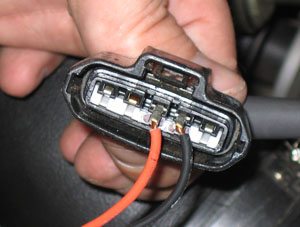
Simply wire a GM Open Element IAT Sensor into your factory wiring harness at the MAF connector. You can poke wires into the MAF connector, or you can cut and splice. Wire one lead of the GM Sensor to the third wire at the MAF Connector, and the other lead of the GM Sensor to the fourth wire at the MAF Connector. The wires should then be folded down over the edge of the MAF connector, and the whole assembly firmly and cleanly wrapped in high quality electrical tape sealing it up. 3M makes tape, such as Super88, that can handle the temps found in engine bays.
After installing the IAT, turn the ignition key on but do not start the engine. Connect to the MSPNP with TunerStudio. Go to the Tools menu and select Calibrate Thermistor Tables. Select Air Temperature Sensor. Select GM from the Common Sensor Values drop down box. Leave the bias resistor setting at 2490.0 ohms. Click Write to Controller. This will update the sensor calibration in the MSPNP.
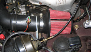
The IAT needs to be located where it will pick up the air temperature after anything in the intake that changes air temperature. So if you are using forced induction, it needs to be downstream of the turbo or supercharger and the intercooler. Here is a picture of an IAT sensor installed in a naturally aspirated car, with a cone filter taking the place of the stock airbox.
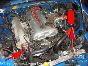
And here's a picture of one way to bypass your AFM and still get your air filter on there (using a popular turbo kit and charge pipe kit), and more importantly, it shows you exactly where to weld the IAT bung to measure air temp AFTER the turbo, and AFTER the IC. You need to know the air temp as it's entering the engine, nothing else will do us much good. If you are running forced induction this is critical, the stock IAT sensor in the AFM will not do.
Note: If you are using the MSPNP with a turbo or supercharger:
After you remove the AFM, install the IAT sensor in the location pictured above which is just before the throttle body inlet. The IAT needs to measure the air temperature as it's entering the engine, not the ambient air temperature in the engine bay as would be measured by the AFM. Only by placing the IAT just before the throttle body can an accurate air temperature measurement be taken AFTER the compressor has heated the air, and the intercooler has cooled it. Accurate air temps are needed for proper fueling and ignition advance calculations.
Sensor Calibration
If you need to recalibrate your temperature sensors, such as after loading firmware, here are the values to use for the stock sensors. These work for both factory CLT and IAT sensors. GM IAT sensors can use the defaults in TunerStudio
| Temperature (degrees F) | Temperature (degrees C) | Resistance (Ohms) | ||
| -4 | -20 | 16150 | ||
| 104 | 40 | 1150 | ||
| 176 | 80 | 330 |
Auxiliary Outputs
| Output | Function | State | Condition (Default) | ||
| Output 2 (Formerly WLED) | Condensor Fan | Off by Default | |||
| Output 1 (Formerly ALED) | Cooling Fan | ON | CLT > 190 |

