MegaSquirt PNP Gen2 Documentation
Model/Vehicle Specific information for model MSPNP2-MK9395 on a 1993-1995 Ford Probe, Mazda MX-6, and Mazda 626 with a 2.5L V6 or 1992-1994 Mazda MX-3 with a 1.8L V6.
Please read all documentation before installing your MegaSquirtPNP EMS, and verify you've followed all steps before starting your engine for the first time.
Physical Installation
All you'll need for a successful install are some basic hand tools. No drilling, or cutting of the original sheet metal or bracketry is required. Because of this you can easily revert back to the stock ECU at anytime if need be. The MSPNP system also includes all the vacuum line and T's needed.
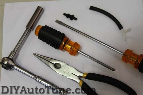
In addition to what is pictured above, you may also want to consider:
-
Zip ties
-
1/4" drive socket set ( metric )
-
Electrical tape ( optional, for securing vacuum line / serial cable )
-
Sharp punch or awl (a small Phillips screwdriver will work as well )
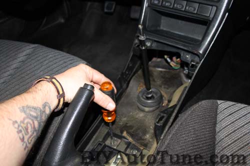
So lets dive right in. Begin by removing the shift knob and passenger's side floor mat, if there is one, to allow access for pulling the carpet back.
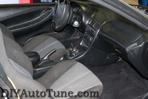
After getting those out of the way, we'll continue by removing the center console and climate control trim panel as the factory ECU is located directly in front of the shifter behind the lower console.
-
Pull the E-brake handle all the way up.
-
Open the cup holder / arm rest storage compartment to gain access to the two screws in the bottom of the compartment. Remove cup holder/armrest from rear of console.
-
Remove the upper center console trim by gently pulling up from the rear of the car, popping the retaining clips loose along the length of the console. ( see below: )
-
Unplug the cigarette lighter harness, and remove the light bulb socket by giving it a twist ¼ turn to the left.
-
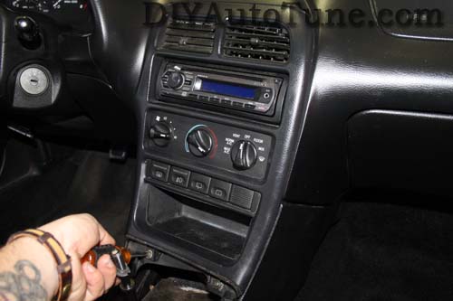
Remove the 2 screws retaining the bottom of the climate control trim panel.
-
Next, pop the trim panel from around the climate control and radio, again being careful with the retaining clips. Then unplug the four colored connectors from the rear of trim panel. ( Black, Orange, White, and Blue )
-
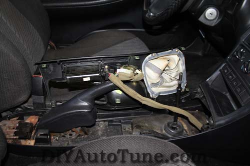
Now, you'll need to remove the lower half of the center console. Open the rear ash tray will remove the two 10mm nuts. Remove the two screws that secure the lower center console just in front of the parking brake handle. Lift the lower console over the parking brake handle and shifter assembly by lifting the rear first and then sliding out of the way.
-
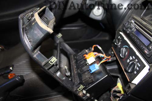
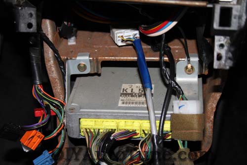
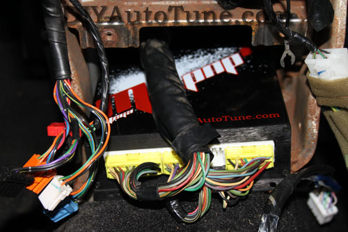
At this point, you'll see the factory ECU mounted in the center of the dash under the climate control and radio head unit. Disconnect the white connector and antenna cable just above the ECU. Remove the two 8mm screws holding the factory ECU bracketry.
-
After unplugging the factory ECU connectors ( Yellow in the above picture ) and removing the factory ECU, we will move on to running the vacuum line for the MegaSquirt PNP MAP sensor. It is important that this be a good strong manifold vacuum source and try to avoid, kinks, hot spots, or anything abrasive that may damage this line. This signal is critical to the proper operation of the MegaSquirt PNP system.
-
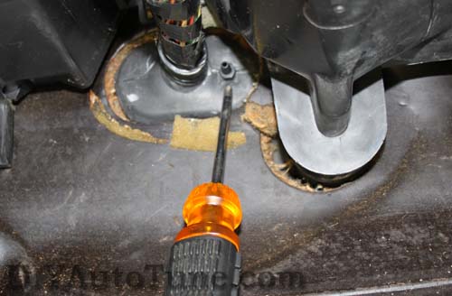
The MAP sensor vacuum hose will pass through the large rubber grommet that the factory wiring harness passes through the fire wall. There is an area just to the right of the factory harness that, using your sharp punch/awl or small screwdriver, you can easily poke a hole through to pass the MAP sensor vacuum hose through. Optionally, install the included threaded bulk head fitting into the hole you just made in the grommet. This will prevent the hose from possibly becoming pinched within the grommet. Otherwise, simply pass the hose through the grommet into the engine bay.
-
Route a piece of vacuum line from here and along the factory harness to the back of the MSPNP. Loosely secure the vacuum line in place against the factory harness with zip ties. Be sure not to pinch the hose by pulling the zip ties too tight. This is also a good time to run your serial communications cable from the rear of the MSPNP to a suitable place that is easily reached out side outside of the console, easily reached once everything is back together.
-
Now you're ready to install the MSPNP unit itself. It fits great in the factory ECU location, but you will have to make a couple of changes. By default, the harness routes underneath the factory ECU. Pull the ECU connector harness free from the plastic clip that holds it to the carpet and route the harness above the top of the MSPNP. Securely mount the MSPNP ECU with zip ties and plug-in the harness connectors.
Moving under the hood:
-
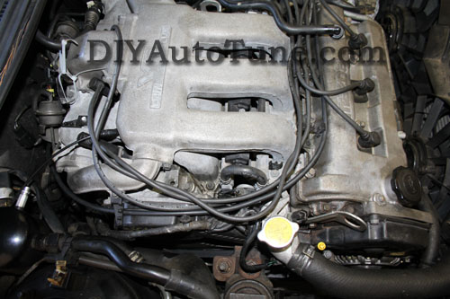
If you used a bulkhead vacuum connector, cut another length of vacuum line and attach it to the connector. Route the line up and to the right (passenger's) side of the engine underneath the spark plug wire retaining clips. This makes for a nice clean install in which you can barely see the vacuum line at all. Again, use zip ties to secure the vacuum line to the ignition cable stands. Continue routing the line to the vicinity of the fuel pressure regulator. You can see the vacuum line for the MAP sensor routed in the picture below. ( black hose against the valve cover directly above the "M" in Mazda and routed around the front of the engine to the grommet passing through the firewall).
-
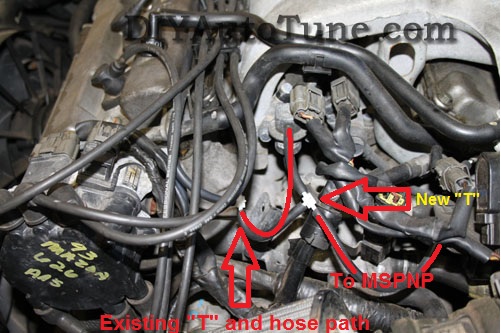
There is already a vacuum "Y" or "T" fitting in place for the fuel pressure regulator and a vacuum rail that runs beneath the throttle body. Use a short piece of hose and another "T" fitting next to the existing fitting.
-
At this point, it is safe to power the ECU up, but please make sure you load the appropriate startup map for your specific engine before attempting to start the vehicle. Using the wrong startup map may result in a no-start condition, or even engine damage if the engine is driven hard before the correct map is loaded.
-
Re-assemble the interior trim panels in the reverse order from above, taking care to install the climate control trim prior to installing the upper half of the center console.
Verifying and Adjusting Base Timing
Because the factory ECU is no longer in control of ignition timing, it will be necessary to make checks to ensure the MSPNP is accurately delivering the proper timing. Improper ignition advance can cause engine damage if improperly set or is left unchecked.
The MSPNP 2 will have a base ignition map loaded and ready to use. However, it is necessary to ensure that the timing advance being commanded by the MegaSquirt is in sync with what the engine is actually seeing. These steps will require the use of a timing light and a laptop with a copy of TunerStudio running.
-
Following the manufacturer's directions, carefully install a timing light on the cylinder #1 spark plug wire. Use all due caution here, as secondary ignition voltage can be as high as 100,000 volts or more. Also ensure that the timing light's cords can not get tangled in a moving engine or burned on hot components.
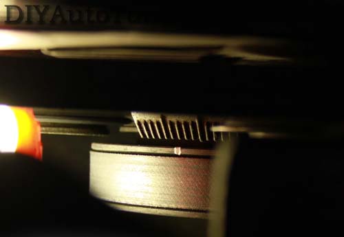
This is the timing mark on our Probe test car. Painted white for clarity. Top Dead Center is the first long mark on the right side of the indicator. ( to the right of the white mark in photo )
-
Make sure your tuning laptop is connected to your MSPNP and start your vehicle. If you have not already done so, go ahead and open up TunerStudio MS or TunerStudio Lite tuning software that you have already downloaded and installed on your laptop. Make sure that your laptop connects to the MSPNP and you are online.
-
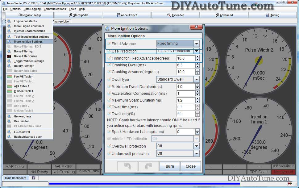
Navigate over to the Ignition Settings -> Ignition Options/Decoder Wheel (For v1.2 MSPNP2s, go to Basic Setup -> More Ignition Settings). This will open the More Ignition Options Menu. If Fixed Advance is set to Use Table, go ahead and set it to Fixed timing. This will tell the MegaSquirt to ignore our Ignition Table and hold a fixed advance. We will then need to enter a value in Timing for Fixed Advance (degrees). The value we enter here will be a static value that our MegaSquirt will use to command ignition timing. 10.0 is the default, and will work here. Burn these changes and close this menu. (Ignore the sections not highlighted in blue rectangles.)
-
Use a timing light to confirm you have 10 degrees of timing on the crank pulley. If you have more timing, increase the number called Tooth #1 Angle under Trigger Wheel Settings. If you have less, decrease the number. For example, if your Tooth #1 Angle is 60 degrees and you're seeing 15 degrees of timing, change Tooth #1 Angle to 55 degrees to bring the timing to a real 10 degrees. Note that these changes only take effect when you turn the ECU off and back on again.
-
Now we need to allow the MSPNP to command timing from the Ignition Table again. Close the Trigger Wheel Settings and go back to Ignition Settings -> Ignition Options/Decoder Wheel (For v1.2 MSPNP2s, go to Basic Setup -> More Ignition Settings). Set your Fixed Advance back to Use Table. Burn and close this menu. The MSPNP is now advancing based on your ignition table.
Fan control
Your MSPNP is set up to use the PM4 - Accel LED output for fan control. The engine coolant temperature is monitored and whenever the temperature exceeds 187 degrees F, the fan will come on. The temperature setting can be changed by selecting menu Boost/Advnaced -> Programmable On/Off Settings (for v1.2 MSPNP2s, select Extended -> Output Port Settings) ; Click "PM4" in the list on the left to find the temperature limit.
VRIS control
The MSPNP is configured to use PT6 - InjectorC to actuate the VRIS1 solenoid and PT7 - Injector D to actuate the VRIS2 solenoid. By default, VRIS1 is active during the range of 3250-6250 RPM. VRIS 2 is active through the range of 4250-6250 RPM.
Optional Wasted Spark
Provisions have been included in the MSPNP to remove ignition control from the distributor and allow ignition from a coil pack.
|
V1.2 PCB |
V1.3 PCB |
||||||||||||||||||||||||
|
|
||||||||||||||||||||||||
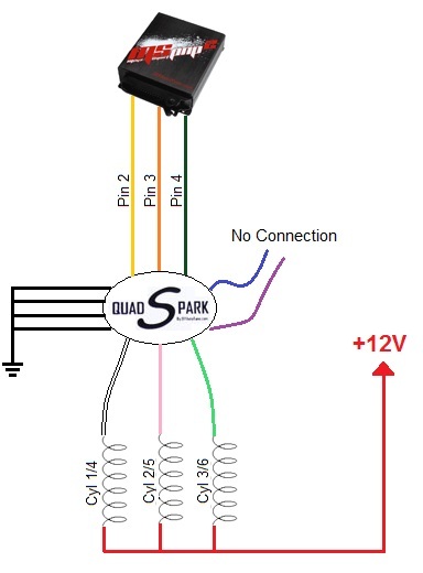
| Please note that these outputs cannot drive a coil directly. An external ignitor such as our QuadSpark would need to be installed between the coils and MSPNP. Coils with built in drivers would also work. Below is an example wiring diagram depicting the installation of a QuadSpark with the MSPNP: | |||||||||||||||||||||||||
 |
 |
||||||||||||||||||||||||
|
Conversely, the QuadSpark can be wired directly to the N76 connector on the front of the MSPNP. The coils wire as depicted below (accessory connector not provided): 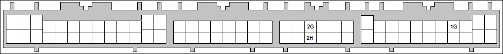
|
|||||||||||||||||||||||||
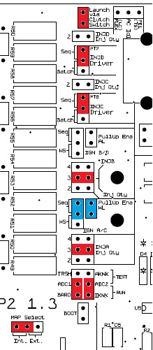
| You'll need to access the main PCB within the MSPNP and jumpers must be installed in the locations below marked in blue. Jumpers denoted in red indicate default jumper locations. | |||||||||||||||||||||||||
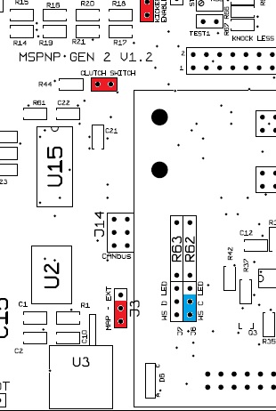 NOTE: The Microsquirt Module must be removed to access this jumper location. |
 |
||||||||||||||||||||||||
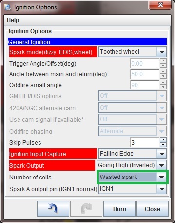
In TunerStudio, select Ignition Settings -> Ignition Options/Decoder Wheel (For v1.2 MSPNP2s, go to Basic Setup -> More Ignition Settings) and change "Number of Coils" to "Wasted Spark".
Removing the Mass Air Flow Meter
Since the MSPNP calculates engine load using a MAP sensor, it ignores the signals generated by the AFM (air flow meter). While not necessary, it is recommended to remove the AFM for a small performance increase. However, the IAT (intake air temperature sensor) is part of the AFM and its signals are used by the MSPNP to adjust fuel trim based on the intake air temperature.
We strongly recommend installing a GM IAT sensor in order to allow the ECU to correct for air temperature variations. The best location for an IAT sensor is just upstream of the throttle body. There are two points on the MSPNP where you can connect an IAT sensor. If racing class rules do not permit you to remove or even unplug the mass air flow sensor, you may wire the IAT to pins 10 and 15 on the 15 pin connector on the MSPNP.
A GM IAT sensor and connector kit can be purchased separately at our online store (part number PNP_IAT-A includes an aluminum bung while part number PNP_IAT-S includes a steel bung).
-
Crimp each of the included terminal ends to a piece of wire, and be sure to use heat shrink and / or electrical tape on the terminals to prevent any moisture, dirt contamination, and or shorting.
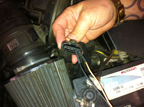
- Plug the wires into the AFM connector as shown below. The sensor is non-polarized, so either wire can plug into either position.
- Route the wires to your Intake Air Temp sensor that you previously installed. On this car in particular, there is a nice space next to the fuse box and under the cruise control unit. ( pictured below ).
- After installing the IAT, turn the ignition key on but do not start the engine. Connect to the MSPNP with TunerStudio. Go to the "Tools" menu and select "Calibrate Thermistor Tables", select "Air Temperature Sensor", and select "GM" from the "Common Sensor Values" drop down box. Leave the bias resistor setting at 2490.0 ohms. Click "Write" to Controller. This will update the sensor calibration in the MSPNP.
Note: If you are using the MSPNP with a turbo or supercharger:
After removing the AFM, install an IAT sensor in the location pictured above which is just before the throttle body inlet. The IAT needs to measure the air temperature as it's entering the engine, not the ambient air temperature in the engine bay as would be measured by the AFM. Only by placing the IAT just before the throttle body can an accurate air temperature measurement be taken AFTER the compressor has heated the air, and the intercooler has cooled it. Accurate air temps are needed for proper fueling and ignition advance calculations.
Sensor Calibration
If you need to recalibrate your temperature sensors, such as after loading firmware, here are the values to use for the stock sensors. These work for both factory CLT and IAT sensors. GM IAT sensors can use the defaults in TunerStudio.
| Temperature (degrees F) | Temperature (degrees C) | Resistance (Ohms) | ||
| -4 | -20 | 15000 | ||
| 104 | 40 | 1100 | ||
| 176 | 80 | 300 |

