MSPNP Pro Documentation
Model/Vehicle specific installation guide for model MSPNPP-EECV-4PM for a 1999-2003 Mazda Protege (1.6, 1.8, 2.0, 2.0T) with a manual transmission.
Please read all documentation before installing your MSPNP EMS and verify that you've followed all steps before starting your engine for the first time.
Physical Installation
All you will need for a successful installation are a few basic hand tools. All fasteners and parts removed in the following steps should be set aside for re-installation as no parts will be discarded.
For a thorough and professional installation, you will need the following items:
-
Ratchet
-
10mm socket
-
Small slotted screw driver (or similar for prying)
-
Needle nose pliers or similar
-
Electric drill
-
1/8" and 13/32" drill bits
-
Awl or sharp punch
-
Side cutters
-
Zip ties
-
Laptop with TunerStudio installed
Stock ECU Removal
-
Disconnect the negative battery cable.
-
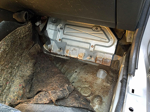
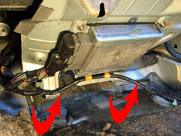
The OEM ECU is located beneath a panel in the passenger side footwell. Begin by removing the floor mat, if present, from the passenger floorboard.
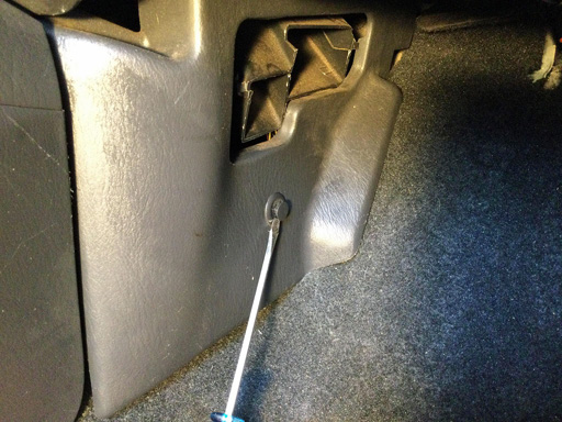
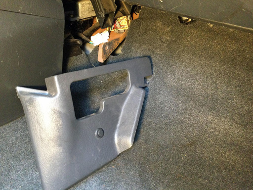
Begin by removing the inboard kick panel. Using a slotted screw driver, pop the center of the plastic rivet out about 1/8". With the rivet released, pull the panel out and away.
-
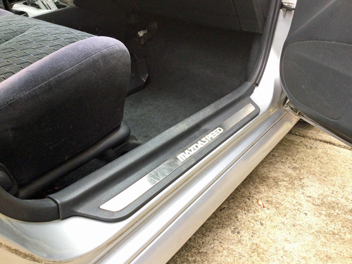
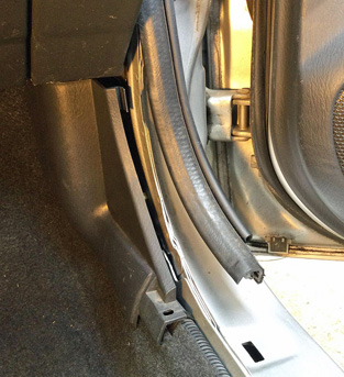
Remove the passenger side door sill by lifting straight up from the rocker at the front end and working toward the back of the car.
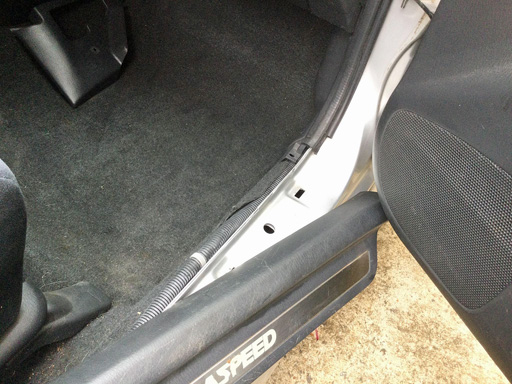
- Partially pull back the rubber door seal.
-
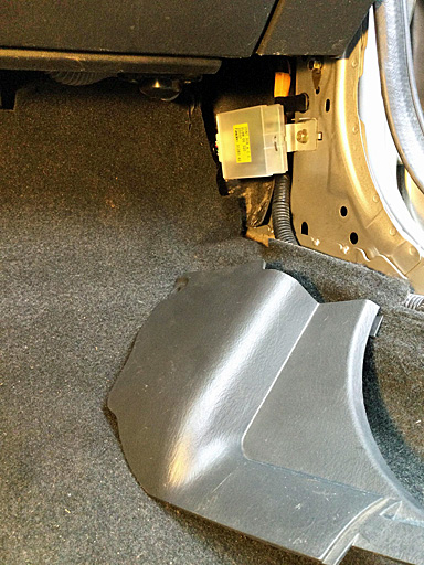
To remove the outer kick panel, use a slotted screw driver to pop the center of the plastic rivet out about 1/8". With the rivet released, pull the panel out and away.
-
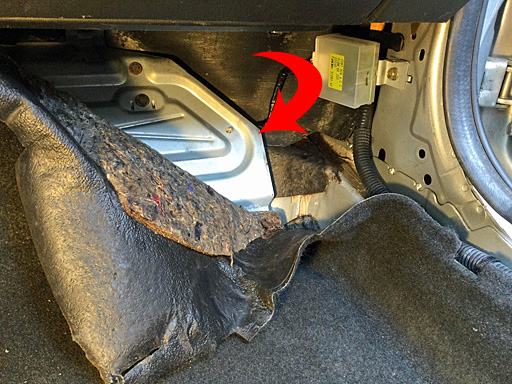
Pull back the carpet starting from the top right of the well. Continue pulling back to fully reveal the ECU cover plate.
-
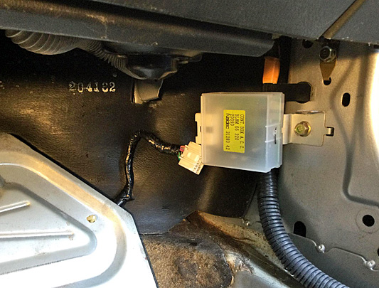
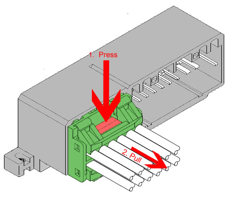
Disconnect the keyless entry receiver module by pressing the retention clip and pulling forward on the top half of the connector. Pull on the connector body and not the wires.
-
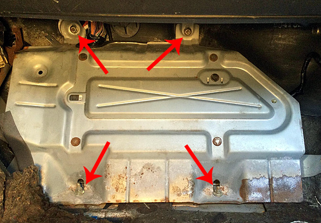
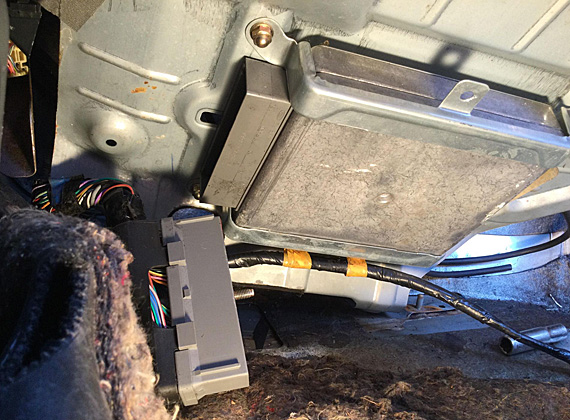
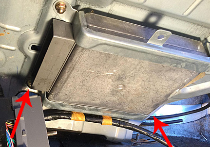
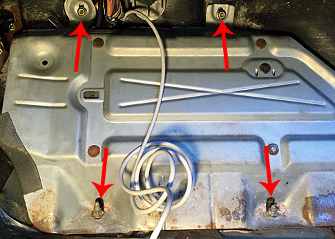
Remove the 4 nuts that secure the plate with a 10mm socket and ratchet.
-
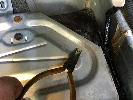
Using needle nose pliers, squeeze the long side of the harness retainer and press it through the plate to release.
-
Lift the bottom of the ECU plate outward above the mounting studs and rotate it toward you and up toward the glove box exposing the ECU. Exercise care as the edges of the plate can be quite sharp.
-
Using a 10mm socket, completely loosen the center bolt that secures the connector to the ECU. Note, the bolt will be retained by the connector and, when it is fully disengaged, the wiring connector will easily pull out of the ECU's connector. Do not force the removal of this connector.
-
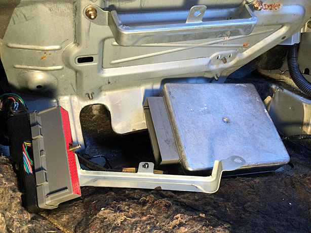
Using a 10mm socket, remove the two acorn nuts that secure the lower ECU bracket. Once removed, the bracket and ECU will fall away from the plate. Remove the ECU and the plate from the vehicle.
-
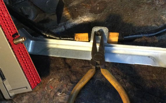
Using needle nose pliers, squeeze the long side of the harness
retainer on the ECU bracket and press it through the hole to
release. Remove the bracket from the car.
MSPNP Attachment
Remove the two acorn nuts securing the second bracket to the ECU plate and remove the bracket.
The brackets will require modification to fit the vacuum port and serial connector on the front of the MSPNP. Using the measurements below, mark the brackets in the locations indicated.
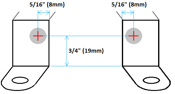
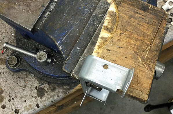
If available, secure the brackets in a vice. Drill a pilot hole in the center of your mark with a 1/8" drill bit. After drilling the pilot hole, increase the hole size using a 13/16" drill bit. Exercise care and drill the holes at a slow speed. If the hole passes into the edge of the bracket while drilling, the bit will grab the edge and likely cause damage. Clean up any burrs or sharp points using a file.
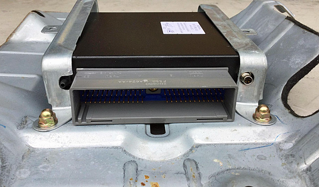
Test the fitment of the modified brackets by installing the MSPNP onto the plate. If the holes were drilled properly, the ECU should fit as displayed below. Note the orientation of the main connector when installing. The printed face of the MSPNP should be against the mounting plate.
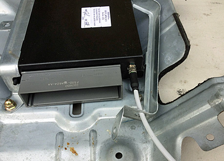
With the modifications to the brackets verified, remove the bracket that is adjacent to the serial connector. Pass the serial cable through the hole in the bracket. Appropriately align the serial cable connector to the connector on the ECU and insert it. Thread the connector collar clockwise until it is finger tight. Slip the bracket over the cable and reseat the bracket over the ECU. Ensure the ECU is pressed all the way forward against the brackets, install the remaining acorn nuts and tighten.
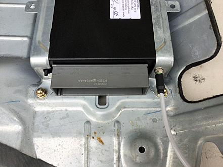
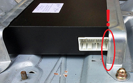
Note, if you choose to make any connections to the options port at the rear of the MSPNP, the wires must be protected from contacting and rubbing the edge of the bracket indicated below.
Final Installation
-
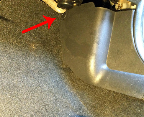
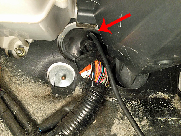
The supplied vacuum hose can be passed through a hole made in a grommet in the firewall. Using an awl or other sharp tool, carefully poke a hole in the location shown from the cabin side of the firewall. Be cautious not to contact or damage any of the wiring in or around the grommet. Once a large enough hole has been established, press the vacuum hose into and through the hole. A small amount of oil or other lubricant will aide in passing the hose through.
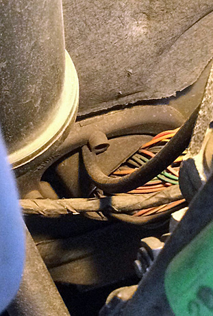
Once a couple inches of hose has been passed through the grommet, pull an additional 2-3 feet oh hose through grommet from the engine bay side of the firewall.
-
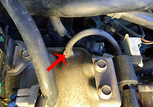
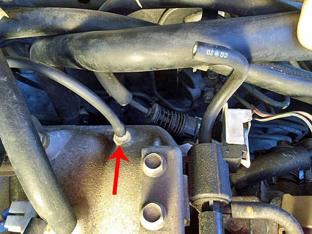
Locate the vacuum port for the fuel pressure regulator on the intake manifold. The MSPNP does not control the solenoid for the fuel pressure regulator, therefore, this hose and its solenoid can be completely removed if desired.
NOTE, there is another port nearby on the intake manifold that connects to the VICS and VTCS solenoids. DO NOT use this port as it is plumbed through a check valve elsewhere on the manifold.
-
Disconnect the FPR vacuum hose from this port. Neatly route the vacuum hose that was passed through the firewall grommet to this location and secure along the way with zip ties. Be sure not to cinch the zip ties too tightly so as to not collapse the vacuum hose. Trim the vacuum hose length and connect it to the vacuum port on the manifold.
-
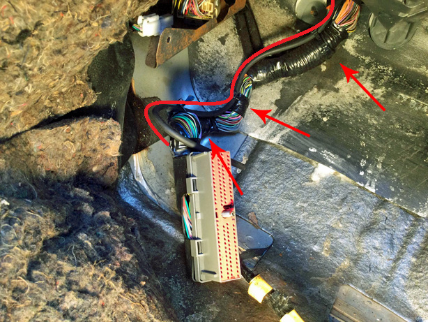
If any optional connections are to be made to the rear options connector, perform those connections now observing the connector pinout at the bottom of this document. When planning the inclusion of optional wiring, leave a sufficient length of wire, roughly about a foot, between the MSPNP and the car's ECU cavity as to allow easy servicing and removal of the MSPNP. Once these connections are complete, connect the option connector to the MSPNP until the connector clicks into place. Neatly bundle the wires for a tidy installation.
-
Back under the dash, route the vacuum line along the ECU wiring harness and secure with zip ties.
-
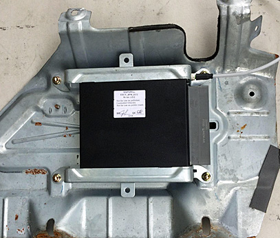
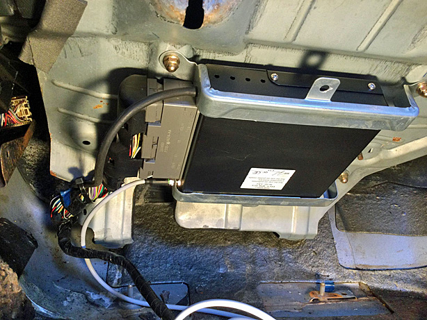
Place the ECU and plate assembly back into the car in the orientation in which it was removed. Insert the original ECU connector into the MSPNP and tighten the center bolt until snug. Do not over-tighten and do not cross thread. The bolt should turn smoothly (about 9 full turns) until the connector is fully seated.
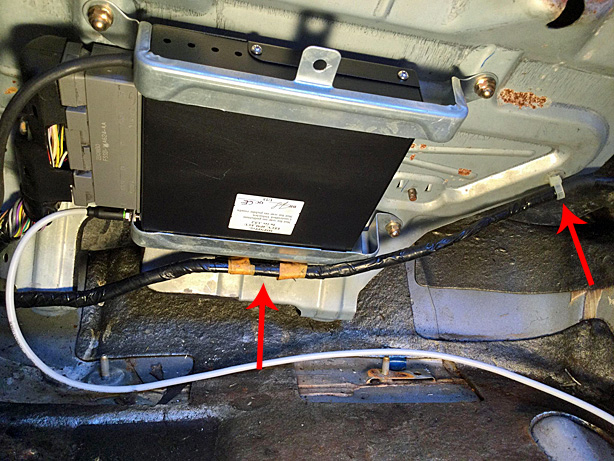
Route the vacuum hose to the port on the MSPNP. Trim it to length while ensuring that it won't be too short. Firmly press the hose onto the vacuum nipple engaging at least the first two barbs.
-
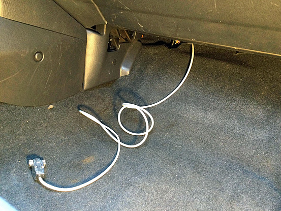
Route the serial cable to a desired location such as the glove box or center console for example.
-
Reattach the harness clips for the keyless entry receiver to the ECU bracket by pushing them into their associated holes until secure.
-
Carefully rotate the ECU plate back into its original location. Remember to exercise care as the edge of the plate are sharp. Reinstall the 4 nuts that secure the plate.
-
Push the floor carpet back into place and reconnect the keyless entry receiver.
Reinstall the inner and outer foot well kick panels and secure with push rivets.
Reseat the door seal along the outer kick panel trim.
-
Reinstall the door sill trim. Light tapping with
may be necessary to properly seat it.
-
Reconnect the negative battery cable.
- At this point, power up, testing, and tuning of the MSPNP can begin.
Removing the Mass Air Flow Meter
Since the MSPNP calculates engine load using a MAP sensor, the air flow meter is no longer needed. While not necessary, it is recommended to remove the AFM for a performance increase. At the very least, the air meter should be unplugged and the connector neatly tied away.
Wideband Sensor Addition
If a wideband Oxygen sensor is to be installed, its signal can be wired into the original O2 sensor wiring in the OE harness or to the EGO pin on the rear options connector. If the options connector is to be used, ensure that the OE narrowband sensors are disconnected.Sensor Calibration
If you need to recalibrate your temperature sensors, such as after loading firmware, below are the values to use for the stock sensors. The bias resistor value is 2490.
| Temperature (degrees F) | Temperature (degrees C) | Resistance (Ohms) |
| Coolant Temperature Sensor (CLT) | ||
| 32 | 0 | 94000 |
| 122 | 50 | 11000 |
| 208.4 | 98 | 2370 |
| Intake Temperature Sensor (IAT) | ||
| 32 | 0 | 94000 |
| 122 | 30 | 11000 |
| 208.4 | 98 | 2370 |
Auxiliary Function I/O Configuration
Below is a listing of specifically purposed functions for auxiliary I/O used on the MS3Pro module and interfaced to the main EEC-V connector:| I/O Point | Function |
| Tach Out | Tachometer |
| High Current 1 (HC1) | Condenser Fan |
| High Current 3 (HC3) | VICS |
| PWM1 | IAC |
| PWM2 | Cooling Fan - High |
| PWM3 | AC Compressor Clutch |
| Spark G | Alternator Field |
| Injector J | Charge Lamp |
| Stepper Out 2 | MIL |
| Digital Switched In 3 (DI3) | AC Request |
| Analog Input 1 (AI1) | MAF Sensor |
| Analog Input 2 (AI2) | Fuel Level |
| Analog Input 3 (AI3) | Baro Sensor |
Optional Configurations
JP5: MAP Sensor Selection

The MSPNP has a built in MAP sensor, but you have the option of using your own that is wired to the rear option connector. Depending on your selection, JP5 should be configured to match. Furthermore, if an external sensor is used, ensure that the scaling is properly set in TunerStudio (Tools -> Calibrate MAP/Baro). Placing the pull-off shunt across the left and center pins, labeled "INT", connects the internal MAP sensor. Placing the pull-off shunt across the center and right pins, labeled "EXT", connects the external sensor wired tot he rear option connector.
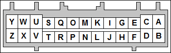
Rear Option Connector
An auxilliary connector and harness is provided to allow you to add functionality to your car. Below is the pinout of the rear connector.An auxilliary connector and harness is provided to allow you to add functionality to your car. Below is the pinout of the rear connector.
| Pin | Function | Default Function | Notes |
| A | Analog Sensor Ground | Sensor Return | |
| B | 5V Vref | Fused at 250mA | |
| C | AIN2 | Fuel Level Sensor | Duplicated on Main Connector Pin 63 |
| D | 12V Supply Out | Fused at 250mA | |
| E | IAT | Duplicated on Main Connector Pin 39 | |
| F | External MAP Sensor | Internal MAP Sensor | |
| G | EGO | Optional Wide Band O2 Sensor, Duplicated on Main Connector Pin 60 | |
| H | Analog Input 1 | MAF Sensor | Duplicated on Main Connector Pin 88 |
| I | CANL | ||
| J | DFIN1 Conditioned | VR Sensors Only, Duplicated on Main Connector Pin 58 | |
| K | CANH | ||
| L | DFIN2 Conditioned | Additional Speed Sensor, VR Sensors Only | |
| M | Digital Input 1 | Optional Flex Fuel | |
| N | Digital Input 4 | ||
| O | Digital Input 2 | ||
| P | DFIN3 | ||
| Q | Digital Input 3 | AC Request Switch | Duplicated on Main Connector Pin 41 |
| R | Tach Out | Instrument Cluster | Duplicated on Main Connector Pin 48 |
| S | Power Ground | ||
| T | High Current Output 3 | VICS | Duplicated on Main Connecor Pin 19 |
| U | High Current Output 1 | Condesner Fan | Duplicated on Main Connecor Pins 17 and 45 |
| V | High Current Output 2 | Duplicated on Main Connecor Pin 82 | |
| W | PWM Output 3 | AC Compressor | Duplicated on Main Connector Pin 69 and 96 |
| X | Injector Output J | Charge Lamp | Duplicated on Main Connecor Pin 42 |
| Y | PWM Output 2 | Cooling Fan - High | Duplicated on Main Connector Pin 46 |
| Z | Injector Output I | Hi-Z Only |
2-10-23 - 1.0

