MSPNP Pro Documentation
Model/Vehicle Specific information for model MSPNP Pro-B8793 on a 1987 - 1993 BMW 325 (E30 Chassis with M20 Engine)
Please read all documentation before installing your MSPNP EMS and verify that you've followed all steps before starting your engine for the first time.
Physical Installation
All you will need for a successful installation are some basic hand tools. All parts removed in the following steps should be set aside for reinstallation as no parts will be discarded.
For a thorough and professional installation, you will need the following items:
-
Ratchet
-
10mm socket
-
Phillips head screwdriver
-
Zip ties
-
Side cutters
-
Laptop with TunerStudio installed
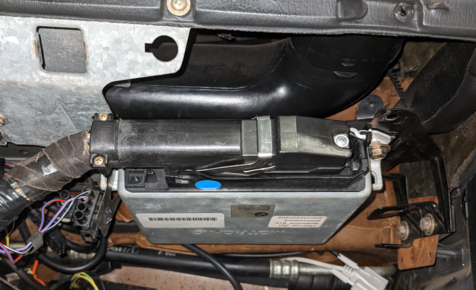
Your stock ECU (also called a DME, for Digital Motronic Engine control unit) is located behind the glove compartment. The following procedure will guide you through its removal and replacement.
- Disconnect the negative battery cable.
-
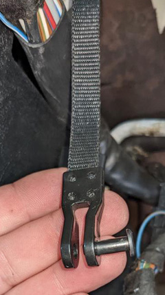
Open the glove box and disconnect the pair of straps on either side by
removing the pin from each clevis.
- Disconnect and remove the flashlight socket (if equipped).
-
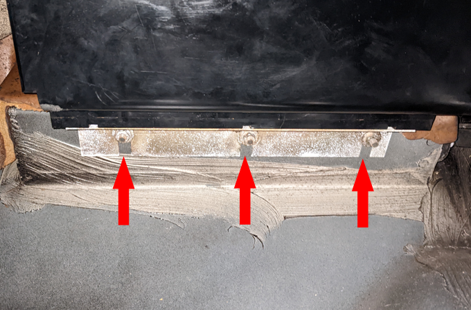
Loosen or remove the 3 nuts
that secure the back of the glove box to the bulkhead with a 10mm socket.
Remove the glove box.
-
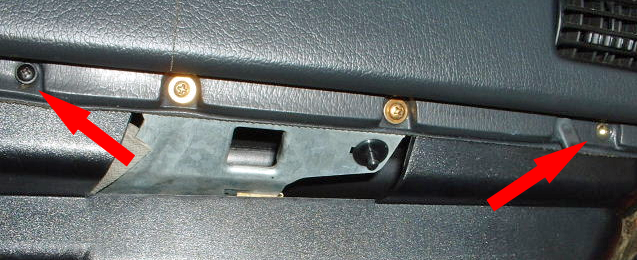
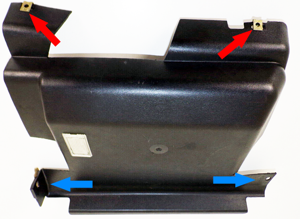
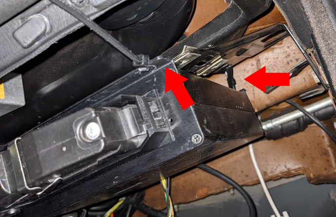
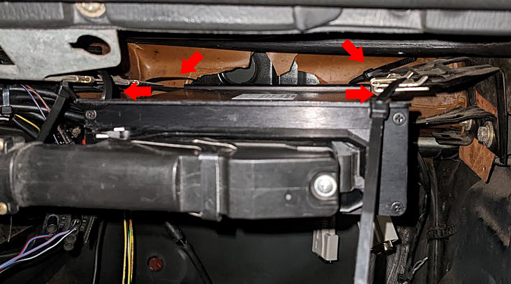
Remove the upper glove box trim. It is secured by two Philips head
screws on the front outer edge (red arrows), and a two plastic quarter turn
retainers toward the rear (blue arrows). Once the trim has been freed, disconnect
the pair of connectors for the light.
-
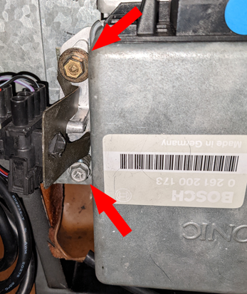
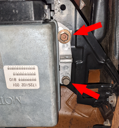
With the glove box and trim out of the way, the ECU is revealed. It is
secured to the dashboard structure by 4 bolts.
-
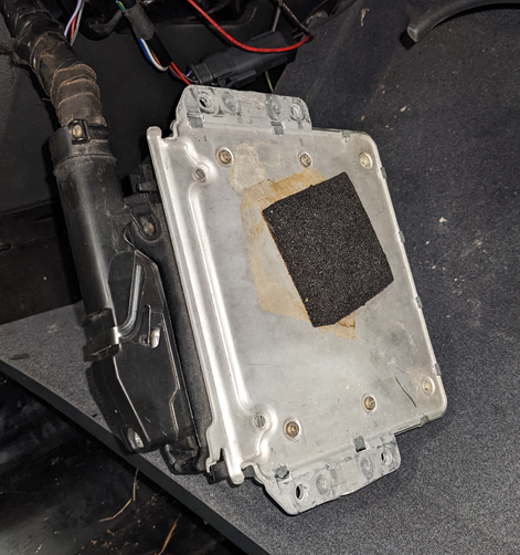
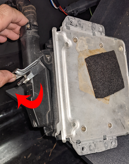
With the DME's 4 screws removed, unlatch and disconnect the wiring harness
connector.
Lift the metal hasp toward the harness side of the connector. As the hasp rotates, it will pry the connector body from the DME.
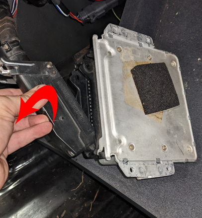
With the harness connector unlatched, rotate it further away from the DME and lift the lower tang out from DME connector.
-
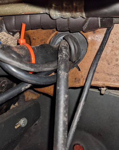
The MAP sensor reference/vacuum hose will pass through an existing grommet
in the firewall. While it will pass through the grommet with room to
spare, extra lubrication will assist in the hose's installation.
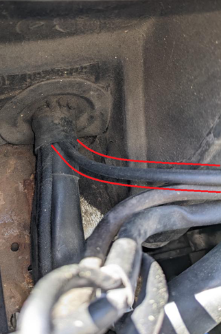
Vacuum hose as viewed from the engine bay.
-
Neatly route the vacuum line to the vacuum port on the side of the intake
manifold. If equipped, remove the rubber cap and connect the MAP
reference line. If this source is already used or the vacuum manifold
only has a single port, splice the included
vacuum tee into the existing vacuum hose that connects to the fuel pressure
regulator.
- Connect the serial cable to the MSPNP.
- Attach and secure the main ECU connector to the MSPNP using the reverse procedure as its removal. If the connector is difficult to seat with the hasp, do not force it. Check and reseat as necessary.
-
The mounting flanges of the MSPNP do not align with the original DME mounting
holes. The easiest way to mount the MSPNP is with zip ties spanning between
its mounting holes and the original DME holes. When securing the zip
ties, try to maintain a position for the MSPNP to be as close to the
firewall as possible with the serial cable attached. This will provide an
adequately secure mounting solution.
- Under the dash, neatly route the vacuum hose to the MSPNP and connect it the
reference port on the back of the enclosure. Ensure that it is routed
in such a way that it won't be pinched or trapped once the glove box is
reinstalled.
- Neatly route the serial cable to a convenient location.
- Reinstall the upper glove box trim using the reverse procedure of its removal.
- Reinstall the glove box using the reverse procedure of its removal.
- Reconnect the negative battery cable.
- At this point, power up, testing, and tuning of the MSPNP can begin.
Verifying and Adjusting Base Timing
It's rare for BWM motors to need a timing adjustment because the trigger wheel is keyed to the crankshaft, but we recommend checking anyway.
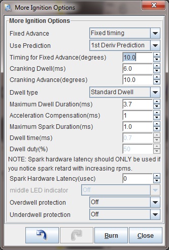
- With the key on, but engine stopped, in TunerStudio, set the MSPNP to fixed timing
mode by going to Ignition Settings -> Ignition Options/Decoder Wheel.
Set Fixed Advance to "Fixed Timing", set Timing for Fixed Advance to 10
degrees, and click the Burn button.
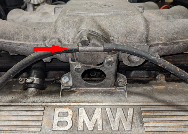
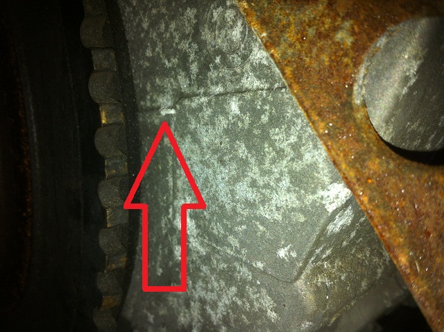
- You'll need to set a dial back timing light to
10 degrees as the BMW timing marks are mostly intended for setting cam
timing. There is a raised marker on the timing belt cover (red arrow,
below) visible from the left side of the car which will line up with a
line between an "O" and a "T" when the engine is at TDC.
- If the timing marks line up with the timing light dialed back to something other than 10 degrees, you will need to adjust the Tooth #1 Angle under Ignition Settings -> Ignition Options/Decoder Wheel. Adding a larger number will retard the timing, while reducing this number will advance the timing. For example, if you set the timing light to 10 degrees and find that you are getting 15 degrees of timing and your Tooth #1 Angle is set to 88 degrees, you will need to change the Tooth #1 Angle to 93 degrees to get correct timing and then verify it with the light.
- After you have confirmed timing is correct, set Fixed Advance back to "Use Table," and click the Burn button so that
the MSPNP will use the ignition table and not the Fixed Timing you used
for the exercise.
Removing the Vane Air Flow Meter
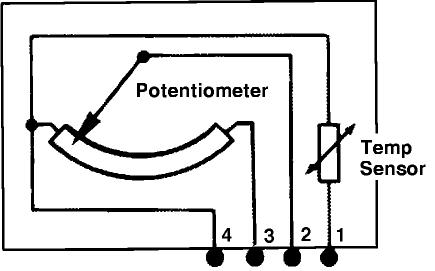
Since the MSPNP by default operates on the principle of speed density, the factory air flow meter can be removed and can be replaced with a length of straight pipe. However, this will require the installation of an air intake temperature sensor as the original is integral to the air meter. The IAT connects to the first and forth pins on the IAT connector, as shown in the graphic below. IAT sensors have no polarity, so it does not matter which wire you connect to which pin.
Simply wire a GM Open Element IAT Sensor (Part number: IATwPiggy) into your factory wiring harness at the AFM connector. You can poke wires into the AFM connector, or you can cut and splice. Wire one lead of the GM Sensor to the first wire at the AFM Connector, and the other lead of the GM Sensor to the fourth wire at the AFM Connector. There are 5 wire slots in the AFM connector, however only 4 have terminals installed. If the wires aren't spliced into the harness (recommended), they can be folded down over the edge of the AFM connector, and the whole assembly firmly and cleanly wrapped in high quality electrical tape sealing it up. 3M has tapes, such as Super88, that can handle the temps found in engine bays.
After installing the IAT, turn the ignition key on but do not start the engine. Connect to the MSPNP with TunerStudio. Go to the Tools menu and select Calibrate Thermistor Tables, select Air Temperature Sensor, and select GM from the Common Sensor Values drop down box. Leave the bias resistor setting at 2490.0 ohms. Click Write to Controller. This will update the sensor calibration in the MSPNP.
Note: If you are using the MSPNP with a turbo or supercharger:
You may choose to delete the AFM and install an IAT sensor in the location pictured above which is just before the throttle body inlet. The IAT needs to measure the air temperature as it's entering the engine, not the ambient air temperature in the engine bay. Only by placing the IAT just before the throttle body can an accurate air temperature measurement be taken AFTER the compressor has heated the air and the intercooler has cooled it. Accurate air temperature measurements are needed for proper fueling and ignition advance calculations.
Installing an aftermarket Variable TPS
Though your vehicle did not come from the factory with a variable throttle position sensor and a VTPS is not required for most of the features of the MSPNP, functionality is included to allow the addition of a variable TPS using the factory wiring harness. Some features require a TPS to be present and it can also help with properly dialing in your acceleration enrichments (though your MSPNP by default will use the MAP signal for this, sometimes TPS based AE is easier to tune).
Below is the pin out to use if you wish to convert to a variable TPS.
| Function | ECU connector pin | TPS connector pin | Wire color | ||
| TPS signal | 52 | 1 | Brown / blue | ||
| Ground | N/A | 2 | Brown | ||
| 5 Volt Reference | 53 | 3 | Brown / black |
If you're not sure which connection on your TPS goes to which wire, check it with an ohmmeter/multimeter. Observe the resistance as the throttle opens and closes. Each pair of pins will behave differently:
-
The resistance between the 5 volt and ground pins will remain constant.
-
The resistance between the ground and signal pins will be low with the throttle closed and high with the throttle wide open.
-
The resistance between the 5 volt and signal pins will be high with the throttle closed and low with the throttle wide open.
Using these rules, you can establish which pin on the TPS goes to which wire. Note that we have not been able to find a TPS that plugs directly into the factory wiring and matches both the plug and the pin out, so you will need to do a bit of splicing to complete this OPTIONAL modification.
Once you have the TPS installed, connect to the MSPNP using TunerStudio with the key on and the engine off. Go to the Tools menu and select Calibrate TPS. With your foot off the throttle, click the "Get Current" button next to the "Closed throttle ADC count" line. Then hold the accelerator to the floor and click the "Get Current" button next to the "Full throttle ADC count" line. The maximum default value is 1023 and the minimum is 0, but it's rare for a TPS to cover the entire range. It's more common to see the closed throttle reading in the 0 to 300 range and the full throttle in the 700 to 1000 range, but as long as the full throttle value is more than the closed throttle value by 200 counts or more, the TPS is functional. If the full throttle count is less than the closed throttle count, switch the ground and reference voltage wires. Once you have obtained adequate numbers, click the Accept button and it will save the values to the ECU.
Sensor Calibration
If you need to recalibrate your temperature sensors, such as after loading firmware, here are the values to use for the stock sensors. These work for both factory CLT and IAT sensors. GM IAT sensors can use the defaults in TunerStudio. The bias resistor value is 2490.
| Temperature (degrees C) | Temperature (degrees F) | Resistance (Ohms) |
| -10 | 14 | 9500 |
| 20 | 68 | 2500 |
| 80 | 176 | 330 |
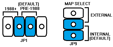
User Definable Internal Jumpers
Several jumpers are located on the lower circuit board inside the MSPNP. These are accessible by removing the top cover and are indicated as depicted below:
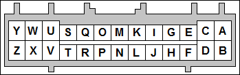
Rear Option Connector
An auxiliary connector and harness is provided to allow you to add functionality to your vehicle. Below is the pin out of the rear connector.
| Pin | MS3 I/O Function | Usage | Notes |
| A | External MAP Sensor | Internal MAP Sensor | |
| B | 5V Vref | Fused at 250mA | |
| C | AIN2 | ||
| D | Analog Sensor Ground | Sensor Return | |
| E | AIN1 | ||
| F | Digital Switched In 2 | ||
| G | EGO |
|
|
| H | Digital Frequency In 1 | 0-5V Square Wave Input | |
| I | Digital In 1 | Optional Flex Fuel | |
| J | High Current Out 2 | ||
| K | CANL | ||
| L | Injector J | ||
| M | CANH | ||
| N | Injector I | ||
| O | Ignition A | 0-5V Output | |
| P | Injector A | Injectors 2, 4, 6 | Duplicated on Main Connector Pin 17. |
| Q | Ignition B | 0-5V Output | |
| R | Injector B | Injectors 1, 3, 5 | Duplicated on Main Connector Pin 16. |
| S | Ignition C | 0-5V Output | |
| T | Injector C | Duplicated on Main Connector Pin 35. | |
| U | Ignition D | 0-5V Output | |
| V | Injector D | Duplicated on Main Connector Pin 34. | |
| W | Ignition E | 0-5V Output | |
| X | Injector E | ||
| Y | Ignition F | 0-5V Output | |
| Z | Injector F | Duplicated on Main Connector Pin 33. |
Main Connector Pin Usage

| Pin | MS3 I/O Function | Usage |
| 1 | Ignition A | Ignition Coil |
| 2 | PGround | Power Ground |
| 3 | Fuel Pump | Fuel Pump Relay |
| 4 | PWM1 | IAC Open |
| 5 | ----- | ----- |
| 6 | TachOut | Tachometer |
| 7 | ----- | ----- |
| 8 | CMP+ | Spare I/O |
| 9 | ----- | ----- |
| 10 | PGround | Power Ground |
| 11 | Knock1 | Knock Sensor |
| 12 | Vref | Sensor +5V Supply |
| 13 | ----- | ----- |
| 14 | PGround | Power Ground |
| 15 | Injector H | CEL |
| 16 | Injector B | Injector Bank 1 (Cyls 1, 2, 5) |
| 17 | Injector A | Injector Bank 2 (Cyls 2, 4, 6) |
| 18 | ----- | Constant 12V Battery Supply |
| 19 | PGround | Power Ground |
| 20 | ----- | ----- |
| 21 | ----- | ----- |
| 22 | PWM2 | IAC Close |
| 23 | High Current 1 | Spare I/O |
| 24 | PGround | Power Ground |
| 25 | ----- | ----- |
| 26 | SGround | Sensor Ground |
| 27 | ----- | Ignition Switch 12V Supply |
| 28 | O2 | Oxygen Sensor Input |
| 29 | DFIN3 | Vehicle Speed Sensor Input |
| 30 | PGround | Power Ground |
| 31 | CMP- | Spare I/O |
| 32 | PWM3 | Fuel Rate Output |
| 33 | Injector F | Spare I/O |
| 34 | Injector D | Spare I/O |
| 35 | Injector C | Spare I/O |
| 36 | ----- | Main Relay Coil Activation |
| 37 | 12V Supply | Main Relay Contacts |
| 38 | ----- | ----- |
| 39 | ----- | ----- |
| 40 | DI3 (Set by JP1) | AC Request (Pre-1988) |
| 41 | DI3 (Set by JP1) | AC Request (1988+) |
| 42 | ----- | ----- |
| 43 | ----- | ----- |
| 44 | IAT | Intake Air Temperature Sensor |
| 45 | CLT | Coolant Temperature Sensor |
| 46 | ----- | ----- |
| 47 | CKP+ | Crankshaft Position Sensor + |
| 48 | CKP- | Crankshaft Position Sensor - |
| 49 | ----- | ----- |
| 50 | ----- | ----- |
| 51 | ----- | ----- |
| 52 | TPS | Throttle Position Sensor |
| 53 | TPS Vref | TPS Vref |
| 54 | ----- | ----- |
| 55 | ----- | ----- |
7-28-23 - 1.1

