MegaSquirt PNP Gen2 Documentation
Model/Vehicle specific installation guide for model MSPNP2-EEC4B8 for a 1994-1995 Ford Mustang 5.0L.
Please read all documentation before installing your MegaSquirtPNP EMS and verify that you've followed all steps before starting your engine for the first time.
This document covers the installation of the updated V2.0 hardware released in August of 2023. Click HERE to view documentation for the legacy V1.2 and V1.3 model ECUs.
Physical Installation
All you'll need for a successful installation are some basic hand tools. No cutting or drilling of the original sheet metal or bracketry is required.
For a thorough and professional installation, you will need the following items:
-
10mm socket and ratchet
-
7/32" socket and ratchet
-
9/32" socket and ratchet
-
Phillips screw driver
-
Zip ties
-
Timing light
-
Laptop with TunerStudio installed
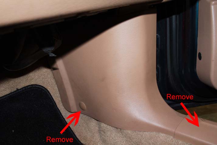
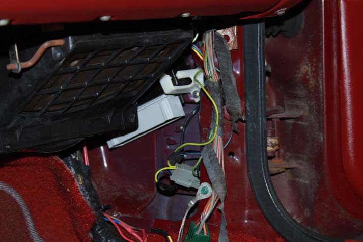
The stock ECU is located in the passenger's side footwell, just behind the kick panel in front of the door. To remove the kick panel, first pull out the plastic plug as depicted below. The plug is fairly tight, but pull evenly and it will pull out. Next, remove the lower door sill cover by grasping the end and firmly pull upward. Afterward, the kick panel simply pulls away.
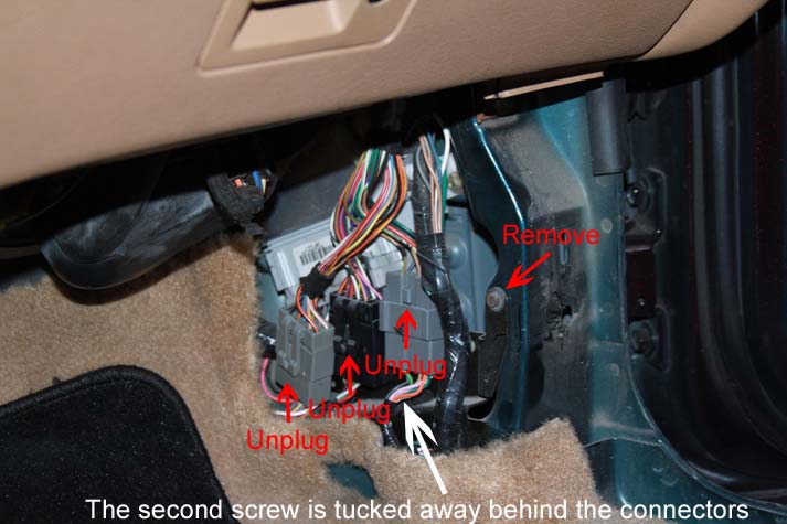
The ECU is tucked away behind a bracket that secures three connectors. Disconnect all three connectors and remove the bracket by removing the two screws that secure it.
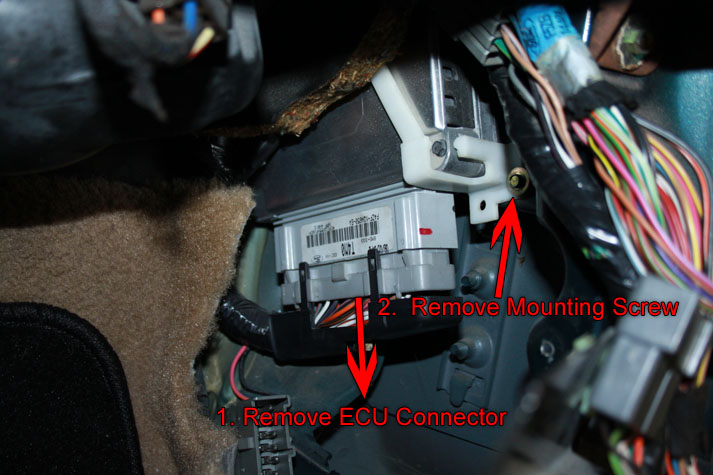
The ECU is held in place by a plastic bracket that is secured by a single screw. First, disconnect the main connector from the ECU by loosening the large bolt in the center of the connector. Note, that the bolt won't come out completely. Wiggle the connector loose from the ECU. Afterwards, remove the screw that secures the ECU bracket. Then with a bit of moving about, the ECU can be pulled free from the car.
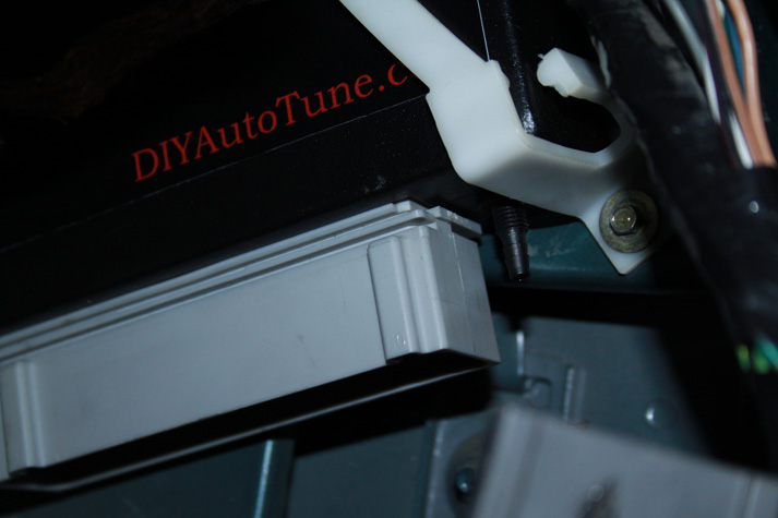
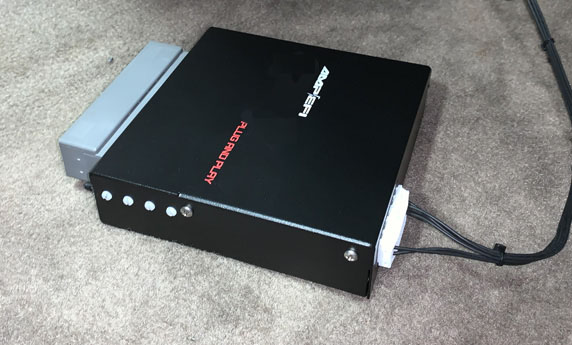
Installation of the MSPNP is the reverse of the factory ECU removal. Simply install it into the place of the original ECU and secure it with the original plastic mounting strap and screw. Please note that the strap fitment will be somewhat tighter due to the location of the vacuum nipple next to the connector. Afterward, reconnect the main harness connector.
Without modification to the factory mounting cradle, the serial cable, knock headphones, and options connector cannot be connected while the MSPNP is installed in place. However, the MSPNP can still be connected to the main harness as well the serial cable outside of the mounting cradle to allow tuning and adjustments if you choose not to modify the cradle.
If any optional connections are to be made to the rear options connector, perform those connections now observing the connector pinout at the bottom of this document. When planning the inclusion of optional wiring, leave a sufficient length of wire, roughly about a foot, between the MSPNP and the car's ECU cavity as to allow easy servicing and removal of the MSPNP. Once these connections are complete, connect the option connector to the MSPNP until the connector clicks into place. Neatly bundle the wires for a tidy installation.
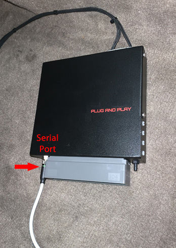
Connect the provided serial cable to the MSPNP and secure by tightening the collar clockwise until snug. When attaching the cable, observe that its pins align properly with the connector on the MSPNP before tightening.
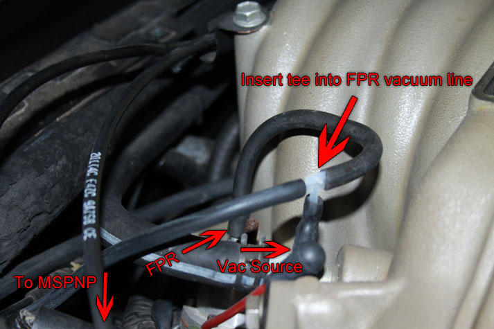
After the MSPNP is mounted, you must run a vacuum line from the engine, through the firewall, and to where the MSPNP resides. A nipple on the side of the intake manifold, just past the throttle body, provides the perfect source for a vacuum reference. A hose small hose connects the fuel pressure regulator to the manifold here. Cut this small hose and insert a tee as shown below. After the tee is installed, connect one end of the vacuum line for the MSPNP here and route it neatly through the engine bay and secure it with zip ties to prevent movement and entanglement.
There is a small rubber grommet in the firewall on the passenger's side corner of the engine bay through which the hose should pass. However, you'll need to remove a few electrical connectors first. The horizontal connector does not need to be disconnected, though it should be removed to allow access to the grommet. Grab the connector at both ends and pull straight up. Rocking back and forth will help in this process. Next, disconnect the large vertical connector by completely loosing the center bolt (the bolt won't come out completely) then pull up.
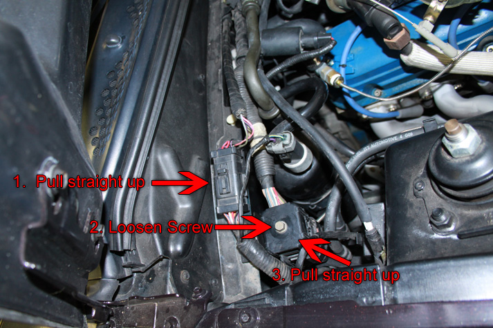
After the connectors are pushed away, CAREFULLY make a slit or hole large enough to pass the vacuum line through. If you use a knife, use extreme caution as there are many wires in this area that you certainly don't want to damage.
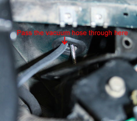
NOTE: Your
car will not have the metallic line passing through the grommet as
pictured above.
Once the vacuum line is routed to the proper location under the dashboard, press it on to the vacuum nipple next to the connector.
Verifying and Adjusting Base Timing
Because the factory ECU is no longer in control of ignition timing, it will be necessary to make checks to ensure the MSPNP is accurately delivering the proper timing. Improper ignition advance can cause engine damage if improperly set or is left unchecked.
The MSPNP will have a base ignition map loaded and ready to use. However, it is necessary to ensure that the timing advance being commanded by the MegaSquirt is in sync with what the engine is actually receiving. These steps will require the use of a timing light and a laptop with a copy of TunerStudio running.
-
Connect a timing light on the cylinder #1 spark plug wire. Use all due caution here, as secondary ignition voltage can be as high as 100,000 volts or more. Also ensure that the timing light's cords can not get tangled in moving engine parts or burned on hot components.
-
Make sure your tuning laptop is connected to your MSPNP and start your vehicle. If you have not already done so, start TunerStudio. Make sure that your laptop connects to the MSPNP and you are online.
-
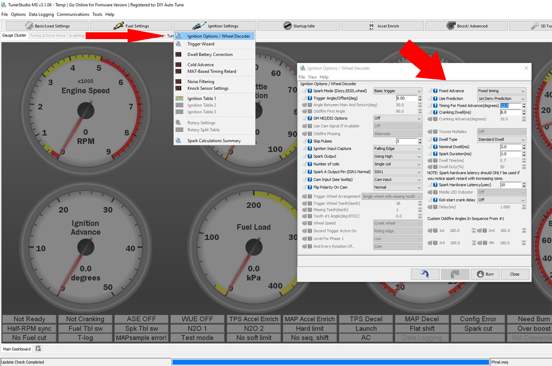
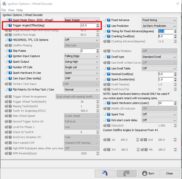
Navigate to the Ignition Settings -> Ignition Options/Decoder Wheel. If "Fixed Advance" is set to "Use Table", set it to "Fixed timing". This will tell the MSPNP to ignore the ignition table and hold a fixed advance angle. Set this value to 12.0 degrees. Burn these changes and close this menu. (Ignore the sections not highlighted in blue rectangles.)
-
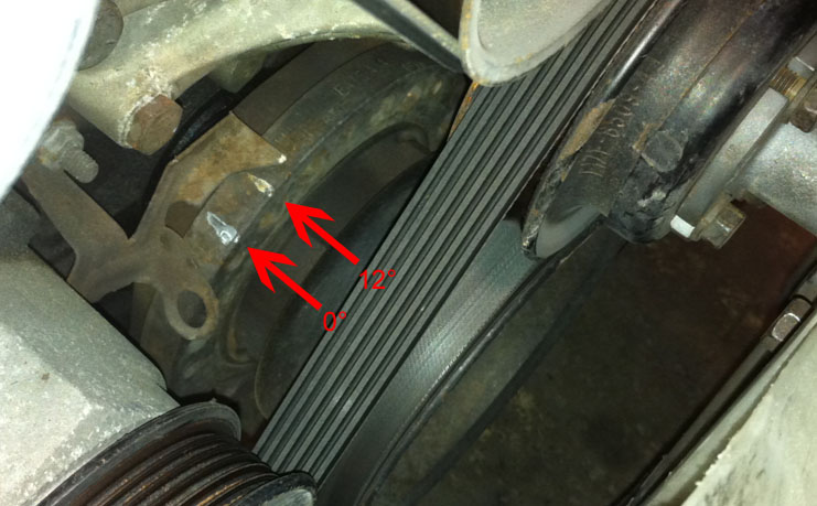
Use a timing light to confirm that you have 12 degrees of timing at the crank pulley -- If you have more timing, decrease the "Trigger Angle". If you have less, increase this value.
-
Once the desired timing angle is achieved, return the "Fixed Advance" setting to "Use Table". Burn and close this menu. Cycle power to the MSPNP (turn the car off and back on). The MSPNP is now commanding timing advance based on the ignition table.
Removing the Mass Air Flow Meter
Since the MSPNP calculates engine load using a MAP sensor, the air flow meter is no longer needed. While not necessary, it is recommended to remove the AFM for a small performance increase. At the very least, the air meter should be unplugged and the connector neatly tied away.
Optional Configurations
Several jumpers are located in various places on the lower circuit board inside the MSPNP. These are accessible by removing the top cover and the default settings are depicted below. Jumper locations J6, J7, and JP3 are platform specific and should not be changed.
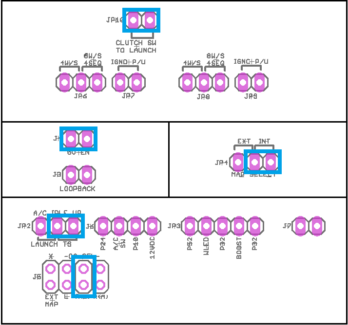
Default settings indicated in blue.
JP2: AC Idle Up
JP2 dictates which input is to be used to command an idle increase when the air conditioner is on. The default input, labeled TS, is "Table Switch". Move the jumper to the LAUNCH location to use the "Launch In" input.
JP4: MAP Select
JP4 selects which MAP sensor will be used. The default setting, labeled INT, uses the internal 4-bar MAP sensor. Move the jumper to the EXT position to use a MAP sensor that is wired to the rear options connector.
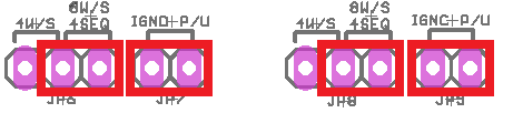
JP6, JP7, JP8, JP9: Wasted Spark Control
Install jumpers on JP6 8W/S, JP7, JP8 8W/S, and JP9 to facilitate the connection of ignition coils for wasted spark. This functionality will require the use of "Output 1" and "Output 2".
Optional settings indicated in red.
On the rear option connector, the
following pins will be used:
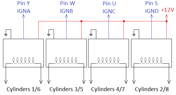
Pin Y: IGNA, cylinders 1 and 6
Pin W:
IGNB, cylinders 3 and 5
Pin U: IGNC (Output 1), cylinders 4 and 7
Pin S: IGND (Output 2) cylinders 2 and 8
Ignition coils with built in drivers (smart coils) must be used. If the desired ignition coils do not have built in drivers, a driver such as our QuadSpark must be installed as well. A basic wiring diagram follows:
JP16: Clutch Switch
Leave this jumper installed.
J3: Loop Back
Connects the serial TX and RX pins together to allow an "echo" of all communication back to the host. Install this only for communication diagnostics.
J4: 5V EN
Enables the 5VDC output on the serial connector for powering devices such as Bluetooth adapters. 400mA max.
J5: O2 Sensor Input
If a wideband oxygen sensor is to be connected to the original sensor connectors, J5 chooses which OE circuit is used. The default selection is the right bank, labeled R(B). To enable the left bank, move the jumper to the L position. If a sensor is to be wired to the rear options connector, remove this jumper completely.
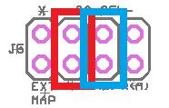
Default settings indicated in blue, optional settings indicated in red.
Rear Option Connector
An auxiliary connector and harness is provided to allow you to add functionality to your car. Below is the pinout of the rear connector. An auxiliary connector and harness is provided to allow you to add functionality to your car. Below is the pinout of the rear connector.
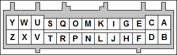
As viewed looking into the ECU connector.
| Pin | Function | Default Function | Notes |
| A | Analog Sensor Ground | Sensor Return | |
| B | Power Ground | ||
| C | EGO | J5 jumper must be removed | |
| D | Knock (ADC2) | ||
| E | IAT | Duplicated on Main Connector Pin 25 | |
| F | External MAP Sensor | Internal MAP Sensor | JP4 jumper must be moved to EXT |
| G | CANL | ||
| H | 5VDC Out | ||
| I | CANH | ||
| J | 12V Supply Out | Fused at 500mA | |
| K | Table Switch In | ||
| L | VRIN2+ | Optional Cam Sensor Input | |
| M | Launch In | ||
| N | Clutch In | Connects to Launch In via JP16 | |
| O | Tach Out | ||
| P | Output 2 | Duplicated on Main Connector Pin 32 | |
| Q | Output 1 | Duplicated on Main Connector Pin 55 | |
| R | Boost | ||
| S | Ignition D | Optional Wasted Spark Cylinders 2 and 8 | |
| T | Injector B | Hi-Z Only | |
| U | Ignition C | Optional Wasted Spark, Cylinders 4 and 7 | |
| V | Injector A | Hi-Z Only | |
| W | Ignition B | Optional Wasted Spark, Cylinders 3 and 5 | |
| X | Injector B | Hi-Z Only | |
| Y | Ignition A | Optional Wasted Spark, Cylinders 1 and 6 | |
| Z | Injector A | Hi-Z Only |
Main Connector Pin Usage
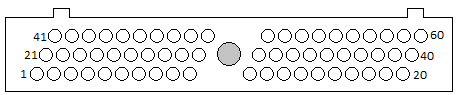
As viewed looking into the ECU connector.
| Pin | Pin Function | Usage |
| 1 | 12V Batt | Constant Supply |
| 2 | ----- | ----- |
| 3 | ----- | ----- |
| 4 | ----- | ----- |
| 5 | 12V Ign | Ignition Switch |
| 6 | Power Ground | Ground |
| 7 | CLT | Coolant Temp Sensor |
| 8 | ----- | ----- |
| 9 | ----- | ----- |
| 10 | A/C Status | A/C Idle Up, see JP2 |
| 11 | ----- | ----- |
| 12 | INJB | Injector 6 |
| 13 | INJB | Injector 7 |
| 14 | INJB | Injector 8 |
| 15 | INJB | Injector 5 |
| 16 | Power Ground | ICM Ground |
| 17 | CEL | Check Engine Lamp |
| 18 | ----- | ----- |
| 19 | ----- | ----- |
| 20 | Power Ground | Ground |
| 21 | IAC | Idle Valve |
| 22 | Fuel Pump | Fuel Pump Relay |
| 23 | ----- | ----- |
| 24 | ----- | ----- |
| 25 | IAT | Intake Air Temp Sensor |
| 26 | 5Vref | Sensor Supply |
| 27 | ----- | ----- |
| 28 | ----- | ----- |
| 29 | ----- | ----- |
| 30 | Clutch Switch | Launch Control |
| 31 | ----- | ----- |
| 32 | Output 2 | High Fan |
| 33 | ----- | ----- |
| 34 | ----- | ----- |
| 35 | INJA | Injector 4 |
| 36 | SPOUT | SPOUT Signal to Ignition Driver |
| 37 | 12V Ign | Ignition Switch |
| 38 | ----- | ----- |
| 39 | INJA | Injector 3 |
| 40 | Power Ground | Ground |
| 41 | ----- | ----- |
| 42 | O2 Sensor, Right | See Jumper J5 |
| 43 | O2 Sensor, Left | See Jumper J5 |
| 44 | ----- | ----- |
| 45 | Ext. MAP | Optional External MAP sensor. See JP4 |
| 46 | Sensor Ground | Sensor Return |
| 47 | TPS | Throttle Position Sensor |
| 48 | ----- | ----- |
| 49 | Power Ground | Ground |
| 50 | ----- | ----- |
| 51 | ----- | ----- |
| 52 | ----- | ----- |
| 53 | ----- | ----- |
| 54 | ----- | ----- |
| 55 | Output 1 | Low Fan |
| 56 | PIP | PIP Signal from Ignition Driver |
| 57 | 12V Ign | Ignition Switch |
| 58 | INJA | Injector 1 |
| 59 | INJA | Injector 2 |
| 60 | Power Ground | Ground |
7-13-23 - 1.2

