MSPNP Pro Documentation
Model/Vehicle specific installation guide for model MSPNPP-EECV-8AM for a 1996-1998 Ford Mustang 4.6L GT/Cobra with a manual transmission.
Please read all documentation before installing your MSPNP EMS and verify that you've followed all steps before starting your engine for the first time.
Physical Installation
All you'll need for a successful installation are some basic hand tools. No cutting of the original sheet metal or bracketry is required. All fastners and parts removed in the following steps should be set aside for reinstallation as no parts will be discarded.
For a thorough and professional installation, you will need the following items:
-
Ratchet
-
5.5mm socket
-
7mm socket
-
8mm socket
-
10mm socket
-
Trim pin removal tool
-
Zip ties
-
Laptop with TunerStudio installed
-
(OPTIONAL) Electric drill with 1/4" drill bit
-
Disconnect the negative battery cable.
-
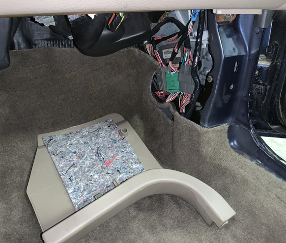
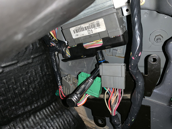
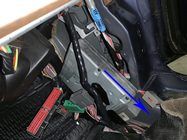
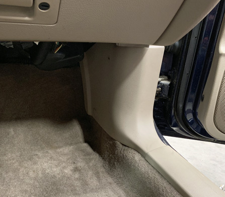
The OEM ECU is located behind the passenger side footwell kick panel.
-
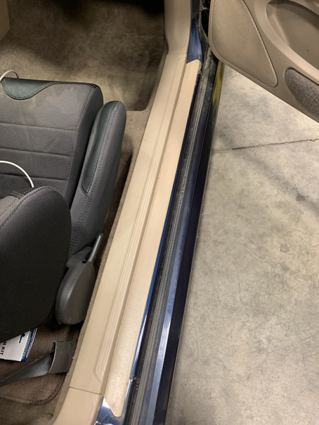
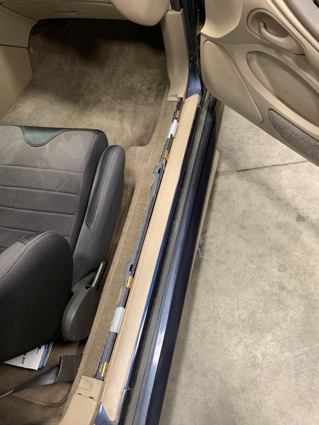
Begin by removing the passenger side door sill by lifting upward from the rocker at the front and working toward the back of the car.
-
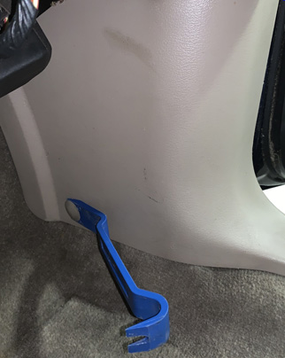
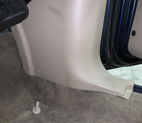
Using a trim tool, remove the kick panel retention pin.
-
Remove the kick panel by sliding it toward the back of the car while lightly pulling inward toward the center or the car.
-
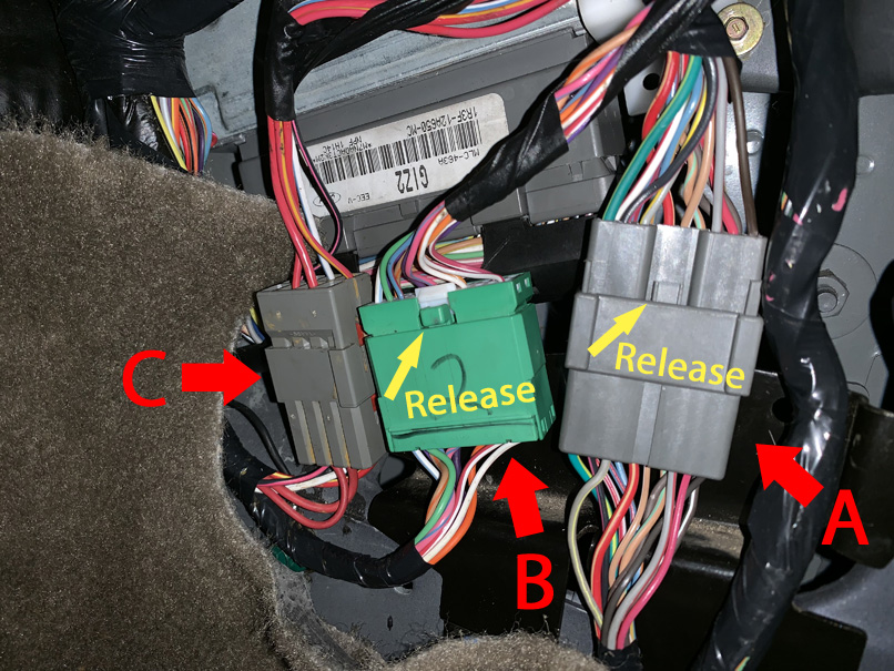
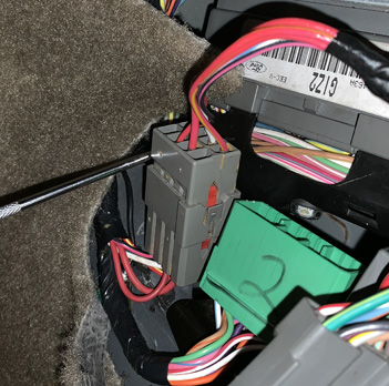
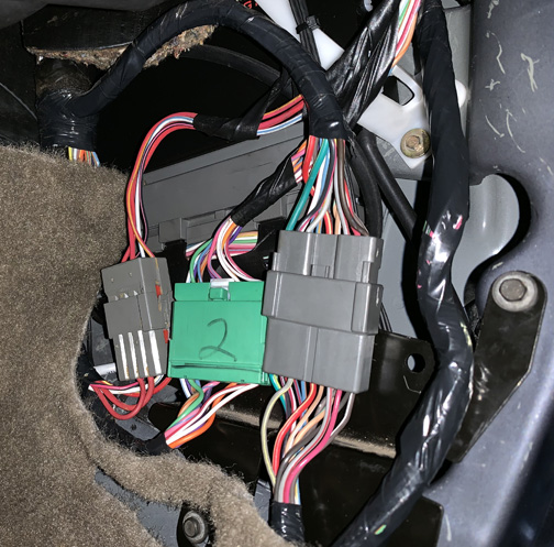
Disconnect connectors A and B by pressing the retention clip and pulling upward on the top half of the connector. Pull on the connector body and not the wires.
-
Disconnect connector C by using a pick and gently pulling away the retention clip on each side of the connector while pulling upward on the top half of the connector. Pull on the connector body and not the wires. These clips are fragile, so use extreme care.
-
Push/tuck the loose connectors out of the way and pull back the carpet
-
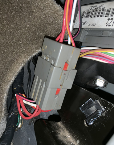
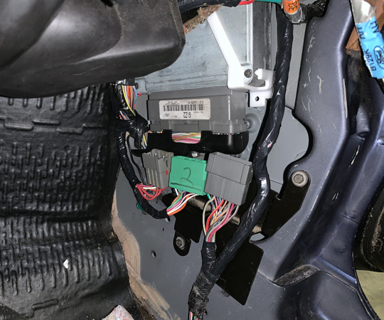
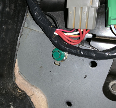
Using an 8mm socket, remove the green ground screw.
-
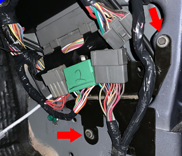
Using a 7mm socket, remove the two screws that secure the connector bracket.
-
Using a 10mm socket, completely loosen the center bolt that secures the connector to the ECU. Note, the bolt will be retained by the connector and, when it is fully disengaged, the wiring connector will easily pull out of the ECU's connector. Do not force the removal of this connector.
-
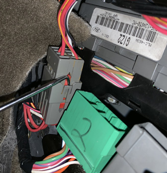
Using a 5.5mm socket, remove the small screw that secures the ECU bracket.
-
Pull the plastic ECU bracket outward (note that you are not actually removing the bracket) enough to free the ECU. Pull the ECU downward and out.
-
If any optional connections are to be made to the rear options connector, perform those connections now observing the connector pinout at the bottom of this document. When planning the inclusion of optional wiring, leave a sufficient length of wire, roughly about a foot, between the MSPNP and the car's ECU cavity as to allow easy servicing and removal of the MSPNP. Once these connections are complete, connect the option connector to the MSPNP until the connector clicks into place. Neatly bundle the wires for a tidy installation.
-
Vacuum Hose Installation Option A
-
The vacuum hose can be passed through a grommet in the firewall through which the air conditioning lines pass. From the engine bay side of the fire wall on the passenger side, work a couple inches of hose through the lower right corner of the grommet.
-
From the footwell, reach up behind the evaporator box and feel around, locating the vacuum hose. Once found, pull 3-feet of hose through.
-
Pull back the gasket flap next to the evaporator drain line and drill a 1/4" hole immediately to the right of the drain line from within the footwell.
-
Install a barbed bulkhead fitting (included) into the hole. Optionally, seal the firewall with RTV
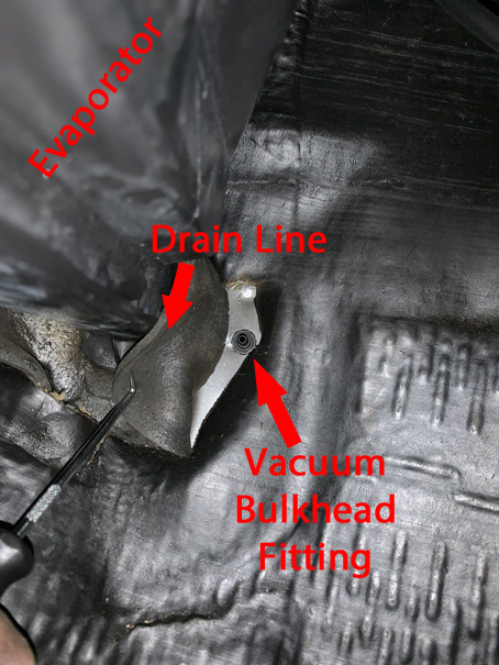
-
Cut a 2 foot length of hose and press it onto the inside nipple of the fitting.
-
Connect the remaining length of hose to the engine bay side of the fitting.
-
For improved retention, secure the vacuum hose to the bulkhead fitting with zip ties.
-
-
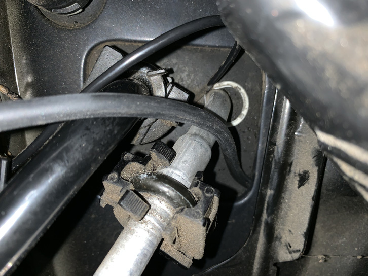
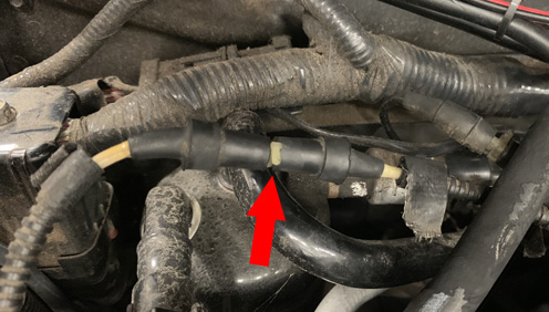
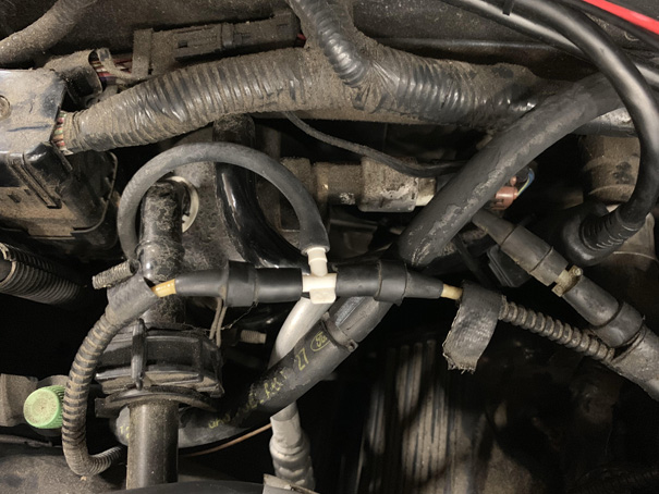
From the engine bay side of the fire wall on the passenger side, locate the white OEM vacuum hose junction as seen in the following image. Separate the two vacuum lines at the junction and remove the coupling tube.
-
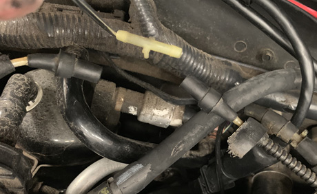
Install the supplied vacuum tee as shown.
-
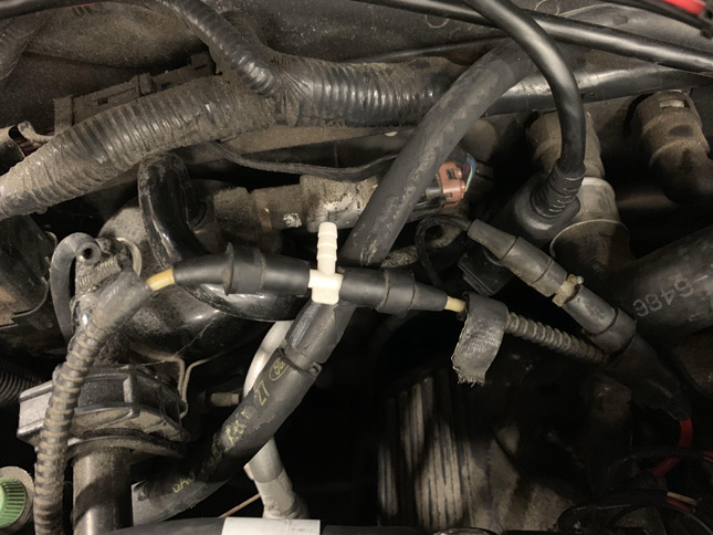
Neatly route the newly installed vacuum hose to the vacuum tee avoiding contact with any heat sources or moving parts. Trim the hose to length and connect it to the third port of the vacuum tee.
-
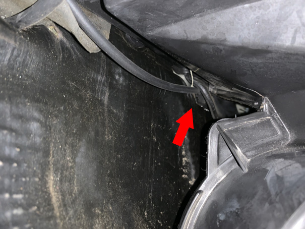
In the passenger footwell, route the vacuum hose as high behind the dashboard as possible and to the pocket where the MSPNP will reside. Route the hose behind the cable bundles.
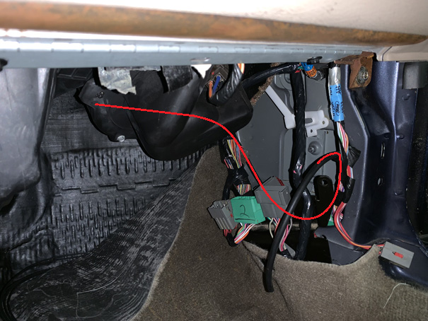
-
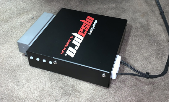
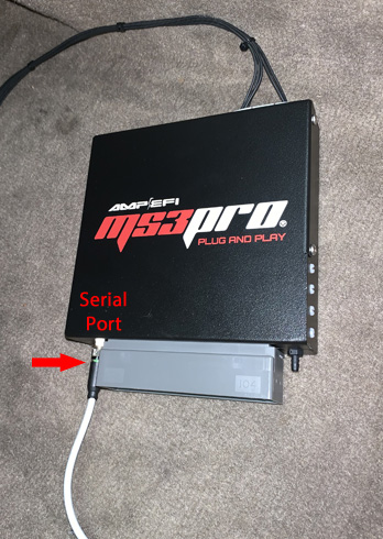
Connect the provided serial cable to the MSPNP and secure by tightening the collar clockwise until snug. When attaching the cable, observe that its pins align properly with the connector on the MSPNP before tightening.
-
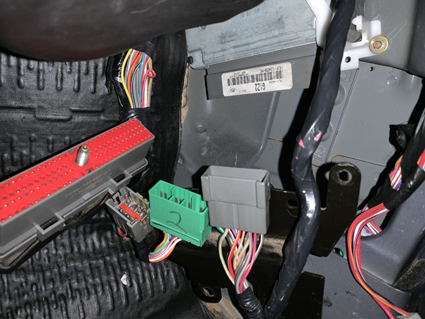
Slide the MSPNP into the original ECU pocket and connect the vacuum hose to the barb on the face of the ECU.
-
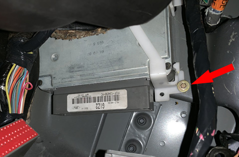
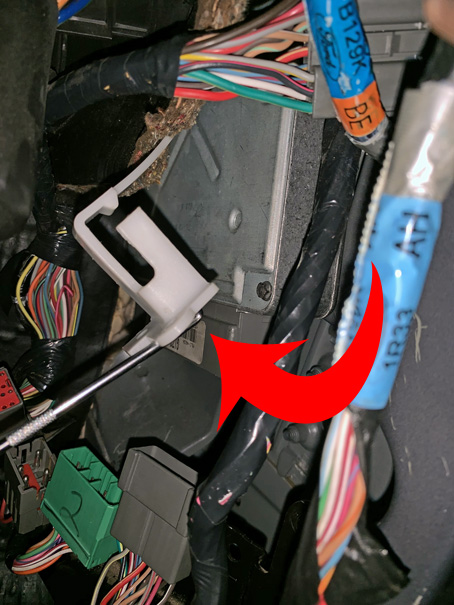
Secure the MSPNP in place with the original plastic bracket. However, do not use the original screw hole in the bracket, but the one just to the left as this ensures the bracket will clear the vacuum nipple. Secure with the previously removed 5.5mm screw.
-
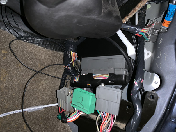
Route the serial cable to the left of the wire bundle and into the floor board. Tuck the excess vacuum hose and optional IO wiring, if installed, into the ECU cavity.
-
Insert the original ECU connector into the MSPNP and tighten the center bolt until snug. Do not over tighten and do not cross thread. The bolt should turn smoothly (about 9 full turns) until the connector is fully seated.
-
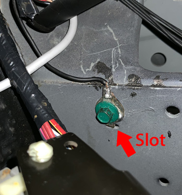
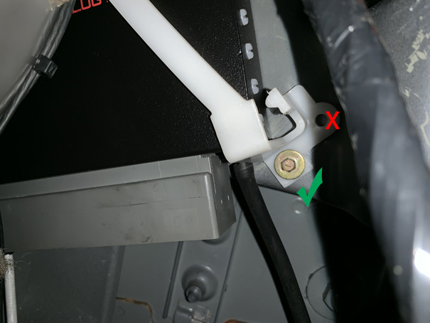
Reinstall the ground wire and ground screw. It is advised to remove any rust or corrosion that may have developed on the contacting surfaces of the ground area before assembling. While tightening with an 8mm socket, ensure the ring terminal's locking tap is properly engaged with the slot just below the screw hole in the car.
-
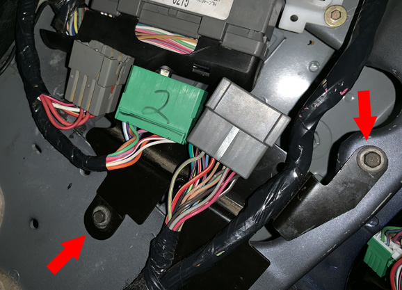
Reinstall the
connector bracket and secure with the two screws previously removed.
Tighten both screws with a 7mm socket.
-
Push the floor carpet back into
place.
-
Reconnect the three wiring connectors ensuring that each
securely clicks into place.
-
Route the serial cable into the
glove box or other suitable location for easy access.
-
Reinstall
the foot well kick panel and secure into place with the previously
removed retention pin.
-
Reinstall the door sill trim. Light tapping with
a rubber mallet may be necessary to properly seat it.
-
Reconnect the negative battery cable.
- At this point, power up, testing, and tuning of the MSPNP can begin.
Removing the Mass Air Flow Meter
Since the MSPNP calculates engine load using a MAP sensor, the air flow meter is no longer needed. While not necessary, it is recommended to remove the AFM for a performance increase. At the very least, the air meter should be unplugged and the connector neatly tied away.
Wideband Sensor Addition
If a wideband Oxygen sensor is to be installed, its signal can be wired into the original O2 sensor wiring in the OE harness or to the EGO pin on the rear options connector. If the options connector is to be used, ensure that the OE narrowband sensors are disconnected.Sensor Calibration
If you need to recalibrate your temperature sensors, such as after loading firmware, below are the values to use for the stock sensors. The bias resistor value is 2490.
| Temperature (degrees F) | Temperature (degrees C) | Resistance (Ohms) |
| Coolant Temperature Sensor (CLT) | ||
| 32 | 0 | 94000 |
| 122 | 50 | 11000 |
| 208.4 | 98 | 2370 |
| Intake Temperature Sensor (IAT) | ||
| 32 | 0 | 94000 |
| 122 | 30 | 11000 |
| 208.4 | 98 | 2370 |
Auxiliary Function I/O Configuration
Below is a listing of specifically purposed functions for auxiliary I/O used on the MS3Pro module and interfaced to the main EEC-V connector:| I/O Point | Function |
| High Current 3 (HC3) | Cooling Fan - Low |
| PWM1 | IAC |
| PWM2 | Cooling Fan - High |
| PWM3 | AC Compressor Clutch |
| Digital Frequency In 1 (DFIN1) | Output Shaft Speed Sensor |
| Digital In 3 (DI3) | AC Request |
| Analog Input 1 | MAF Sensor |
| TACHOUT | Tachometer |
| IAC2 | CEL |
Optional Configurations
Two configuration jumpers are located on the lower, black circuit board inside the MSPNP. It is accessible by removing the top cover and is indicated as depicted below:
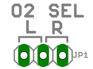
JP1: Left/Right Narrow Band O2 Sensor Selection
JP4: Map Sensor Selection
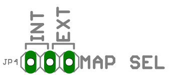
The MSPNP has a built in MAP sensor, but you have the option of using your own that is wired to the rear option connector. Depending on your selection, JP5 should be configured to match. Furthermore, if an external sensor is used, ensure that the scaling is properly set in TunerStudio (Tools -> Calibrate MAP/Baro). Placing the pull-off shunt across the left and center pins, labeled "INT", connects the internal MAP sensor. Placing the pull-off shunt across the center and right pins, labeled "EXT", connects the external sensor wired tot he rear option connector.
Rear Option Connector
An auxilliary connector and harness is provided to allow you to add functionality to your car. Below is the pinout of the rear connector.An auxilliary connector and harness is provided to allow you to add functionality to your car. Below is the pinout of the rear connector.
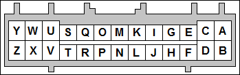
| Pin | Function | Default Function | Notes |
| A | Analog Sensor Ground | Sensor Return | |
| B | 5V Vref | Fused at 250mA | |
| C | AIN2 | Fuel Pressure Sensor | Duplicated on Main Connector Pin 63 |
| D | 12V Supply Out | Fused at 250mA | |
| E | IAT | Duplicated on Main Connector Pin 39 | |
| F | External MAP Sensor | Internal MAP Sensor | |
| G | EGO | Optional Wide Band O2 Sensor | |
| H | Analog Input 1 | MAF Sensor | Duplicated on Main Connector Pin 88 |
| I | CANL | ||
| J | DFIN1 Conditioned | OSS+ VR | VR Sensors Only, Duplicated on Main Connector Pin 84 |
| K | CANH | ||
| L | DFIN2 Conditioned | Additional Speed Sensor, VR Sensors Only | |
| M | Digital Input 1 | Optional Flex Fuel | |
| N | Digital Input 4 | ||
| O | Digital Input 2 | ||
| P | DFIN3 | ||
| Q | Digital Input 3 | AC Request Switch | Duplicated on Main Connector Pin 41 |
| R | Tach Out | Instrument Cluster | |
| S | Power Ground | ||
| T | High Current Output 3 | Low Cooling Fan | Inverted on Main Connector Pin 45 |
| U | High Current Output 1 | ||
| V | High Current Output 2 | ||
| W | PWM Output 3 | AC Compressor | Duplicated on Main Connector Pin 69 |
| X | Injector Output J | Hi-Z Only | |
| Y | PWM Output 2 | Cooling Fan - High | Duplicated on Main Connector Pin 46 |
| Z | Injector Output I | Hi-Z Only |
12-8-22 - 1.4

